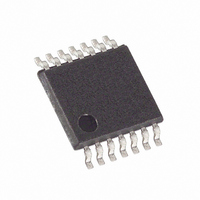
DS1807E+ Maxim Integrated Products, DS1807E+ Datasheet - Page 7

DS1807E+
Manufacturer Part Number
DS1807E+
Description
IC POT ADDRESS 2X AUDIO 14-TSSOP
Manufacturer
Maxim Integrated Products
Datasheet
1.DS1807S.pdf
(13 pages)
Specifications of DS1807E+
Taps
64 + Mute
Resistance (ohms)
45K
Number Of Circuits
2
Temperature Coefficient
750 ppm/°C Typical
Memory Type
Volatile
Interface
I²C, 2-Wire Serial
Voltage - Supply
2.7 V ~ 5.5 V
Operating Temperature
-40°C ~ 85°C
Mounting Type
Surface Mount
Package / Case
14-TSSOP
Resistance In Ohms
45K
Number Of Pots
Dual
Taps Per Pot
64
Resistance
45 KOhms
Wiper Memory
Volatile
Digital Interface
Serial (2-Wire)
Operating Supply Voltage
2.7 V to 5.5 V
Supply Current
40 uA
Maximum Operating Temperature
+ 85 C
Minimum Operating Temperature
- 40 C
Mounting Style
SMD/SMT
Supply Voltage (max)
5.5 V
Supply Voltage (min)
2.7 V
Tolerance
20 %
Lead Free Status / RoHS Status
Lead free / RoHS Compliant
When the master has received the ACKNOWLEDGE from the DS1807, the master can then begin to
receive potentiometer wiper data. The value of the potentiometer-0 wiper position will be the first
returned from the DS1807. Once the 8 bits of the potentiometer-0 wiper position have been transmitted,
the master will need to issue an ACKNOWLEDGE, unless it is the only byte to be read, in which case the
master issues a NOT ACKNOWLEDGE. If desired the master may stop the communication transfer at
this point by issuing the STOP condition. However, if the value of the potentiometer-1 wiper position
value is needed communication transfer can continue by clocking the remaining eight bits of the
potentiometer-1 value, followed by a NOT ACKNOWLEDGE. Final communication transfer is
terminated by issuing the STOP command. Again the flow of the read operation is presented in Figure 6.
WRITING THE DS1807
A data flow diagram for writing the DS1807 is shown in Figure 7. The DS1807 has three commands
which are used to change the position(s) of the wiper. These include write pot-0, write pot-1, and write
pot-0/1. The write pot-0 command allows the user to write the value of potentiometer-0 and as an option
the value of potentiometer-1. The write-1 command allows the user to write the value of potentiometer-1
only. The last write command, write-0/1, allows the user to write both potentiometers to the same value
with one command and one data value being issued.
All the write operations begin with a START condition. Following the START condition, the master
device will issue the control byte. The read/write bit of the control byte will be set to 0 for writing the
DS1807. Once the control byte has been issued and the master receives the acknowledgment from the
DS1807, the command byte is transmitted to the DS1807. As mentioned above, there exist three write
operations that can be used with the DS1807. The binary value of each write command is shown in Figure
7 and also in Table 1.
2-WIRE WRITE COMMAND WORDS Table 1
Once the DS1807 has received the command byte, it will responds with an ACKNOWLEDGE. The
master can then write the corresponding data-byte associated with the command byte. When the DS1807
has received the data byte(s), it will respond with an acknowledgement. At this point the master device
should respond with the STOP condition.
ZERO-CROSSING DETECTION COMMAND WORD
Zero-crossing detection was described under the operation section of this document. As stated earlier,
zero-crossing detection must be deactivated or activated under software control. The command words
used to activate or deactivate the zero-crossing detection feature is shown in Table 2
ZERO-CROSSING DETECTION COMMAND WORDS Table 2
Á Á Á Á Á Á Á Á
Á Á Á Á Á Á Á Á
Write Potentiometer-0
Write Potentiometer-1
Write Both Pots
Activate Zero-Crossing
Deactivate Zero-Crossing
COMMAND
COMMAND
7 of 13
Á Á Á Á Á Á Á
COMMAND VALUE
COMMAND VALUE
101010 01
101010 10
101011 11
101111 01
101111 10
.
110499
DS1807


