MAX5451EUD+ Maxim Integrated Products, MAX5451EUD+ Datasheet - Page 8
MAX5451EUD+
Manufacturer Part Number
MAX5451EUD+
Description
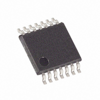
IC DGTL POT DUAL 256-TAP 14TSSOP
Manufacturer
Maxim Integrated Products
Datasheet
1.MAX5451EUD.pdf
(12 pages)
Specifications of MAX5451EUD+
Taps
256
Resistance (ohms)
10K
Number Of Circuits
2
Temperature Coefficient
35 ppm/°C Typical
Memory Type
Volatile
Interface
Up/Down
Voltage - Supply
2.7 V ~ 5.5 V
Operating Temperature
-40°C ~ 85°C
Mounting Type
Surface Mount
Package / Case
14-TSSOP
Resistance In Ohms
10K
Number Of Pots
Dual
Taps Per Pot
256
Resistance
10 KOhms
Wiper Memory
Volatile
Digital Interface
Up/Down
Operating Supply Voltage
2.7 V to 5.5 V
Supply Current
2 uA
Maximum Operating Temperature
+ 85 C
Minimum Operating Temperature
- 40 C
Description/function
Dual, 256-Tap, Up/Down Interface Digital Potentiometers
Mounting Style
SMD/SMT
Supply Voltage (max)
5.5 V
Supply Voltage (min)
2.7 V
Tolerance
25 %
Lead Free Status / RoHS Status
Lead free / RoHS Compliant


The MAX5450–MAX5455 contain two independent
resistor arrays each with 255-resistive elements. 256-
tap points are accessible to the wiper along the resistor
arrays between H and L
cuitry sets the wiper to midscale (position 127) at
power-up.
Logic inputs CS, U/D, and INC determine the wiper
position of the MAX5450–MAX5455. With CS low and
U/D high, a high-to-low (falling edge) transition on INC,
increments the internal counter, which increases the
resistance between W and L. When both CS and U/D
are low, a high-to-low INC transition decrements the
internal counter, decreasing the resistance between W
and L (Figure 1). The wiper performs a make-before-
break transition ensuring that there is never an open
circuit during a transition from one resistor tap to anoth-
er. When the wiper is at either end (max/min) of the
resistor array, additional transitions in the direction of
the endpoint will not change the counter value (the
counter will not wrap around).
The MAX5450/MAX5452/MAX5454 are similar to the
MAX5451/MAX5453/MAX5455 except for internal con-
nections. The MAX5450/MAX5452/MAX5454 internally
connect INC1 to INC2, U/D1 to U/D2, W1 to H1, and
W2 to H2 (Figures 3 and 4). The internal connections
configure the MAX5450/MAX5452/MAX5454 to be vari-
able resistors.
Dual, 256-Tap, Up/Down Interface,
Digital Potentiometers
Figure 1. Digital Interface and Timing diagram
8
_______________________________________________________________________________________
U/D_
INC_
CS_
W_
Detailed Description
(Figure 2). Power-on reset cir-
t
DI
t
CI
t
IL
t
ID
The MAX5450–MAX5455 are ideal for adjustable volt-
age or adjustable gain circuits where accurate
adjustable resistances are required.
Figure 5 shows the MAX5450/MAX5452/MAX5454 with
a MAX4250 low-noise op amp to fine-tune a current to
voltage converter. The physical sizes of both devices
minimize circuit space.
Figures 6a and 6b shows the MAX5450–MAX5455 digi-
tally adjusting the gain of the MAX4493 general-pur-
pose, dual supply op amp. Figure 6a shows the
MAX5450/MAX5452/MAX5454 variable resistor in
series with a resistor to ground to form the adjustable
gain control. Figure 6b shows the MAX5451/MAX5453/
MAX5455 as a 3-terminal potentiometer. In these appli-
cations the low 5ppm/°C ratiometric tempco allows for
a very stable adjustable gain over temperature.
In Figure 7, the MAX5450/MAX5452/MAX5454 is shown
digitally adjusting the output voltage of the MAX8866
dual linear regulator. In this circuit, the MAX5450/
MAX5452/MAX5454 is connected in series with a resis-
tor to ground to form the adjustable feedback stage.
The 8-bit MAX5450/MAX5452/MAX5454 allows precise
tuning of the output voltage.
t
IW
Adjustable Current to Voltage Converter
t
IH
Applications Information
Adjustable Linear Regulator
t
IC
Adjustable Gain Amplifier
Related parts for MAX5451EUD+
Image
Part Number
Description
Manufacturer
Datasheet
Request
R

Part Number:
Description:
Dual, 256-Tap, Up/Down Interface, Digital Potentiometers
Manufacturer:
MAXIM [Maxim Integrated Products]
Datasheet:
Part Number:
Description:
+5V, Serial-Input, Voltage-Output, 14-Bit DACs
Manufacturer:
MAXIM [Maxim Integrated Products]
Datasheet:

Part Number:
Description:
MAX7528KCWPMaxim Integrated Products [CMOS Dual 8-Bit Buffered Multiplying DACs]
Manufacturer:
Maxim Integrated Products
Datasheet:
Part Number:
Description:
Single +5V, fully integrated, 1.25Gbps laser diode driver.
Manufacturer:
Maxim Integrated Products
Datasheet:
Part Number:
Description:
Single +5V, fully integrated, 155Mbps laser diode driver.
Manufacturer:
Maxim Integrated Products
Datasheet:
Part Number:
Description:
VRD11/VRD10, K8 Rev F 2/3/4-Phase PWM Controllers with Integrated Dual MOSFET Drivers
Manufacturer:
Maxim Integrated Products
Datasheet:
Part Number:
Description:
Highly Integrated Level 2 SMBus Battery Chargers
Manufacturer:
Maxim Integrated Products
Datasheet:
Part Number:
Description:
Current Monitor and Accumulator with Integrated Sense Resistor; ; Temperature Range: -40°C to +85°C
Manufacturer:
Maxim Integrated Products
Part Number:
Description:
TSSOP 14/A°/RS-485 Transceivers with Integrated 100O/120O Termination Resis
Manufacturer:
Maxim Integrated Products
Part Number:
Description:
TSSOP 14/A°/RS-485 Transceivers with Integrated 100O/120O Termination Resis
Manufacturer:
Maxim Integrated Products
Part Number:
Description:
QFN 16/A°/AC-DC and DC-DC Peak-Current-Mode Converters with Integrated Step
Manufacturer:
Maxim Integrated Products
Part Number:
Description:
TDFN/A/65V, 1A, 600KHZ, SYNCHRONOUS STEP-DOWN REGULATOR WITH INTEGRATED SWI
Manufacturer:
Maxim Integrated Products
Part Number:
Description:
Integrated Temperature Controller f
Manufacturer:
Maxim Integrated Products
Part Number:
Description:
SOT23-6/I°/45MHz to 650MHz, Integrated IF VCOs with Differential Output
Manufacturer:
Maxim Integrated Products
Part Number:
Description:
SOT23-6/I°/45MHz to 650MHz, Integrated IF VCOs with Differential Output
Manufacturer:
Maxim Integrated Products