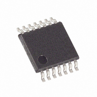
MAX5482EUD+ Maxim Integrated Products, MAX5482EUD+ Datasheet - Page 16

MAX5482EUD+
Manufacturer Part Number
MAX5482EUD+
Description
IC DGTL POT 10BIT NV 14-TSSOP
Manufacturer
Maxim Integrated Products
Datasheet
1.MAX5481EUD.pdf
(20 pages)
Specifications of MAX5482EUD+
Taps
1024
Resistance (ohms)
50K
Number Of Circuits
1
Temperature Coefficient
35 ppm/°C Typical
Memory Type
Non-Volatile
Interface
SPI, 3-Wire Serial
Voltage - Supply
2.7 V ~ 5.25 V, ±2.5 V ~ 5.25 V
Operating Temperature
-40°C ~ 85°C
Mounting Type
Surface Mount
Package / Case
14-TSSOP
Resistance In Ohms
50K
Number Of Pots
Single
Taps Per Pot
1024
Resistance
50 KOhms
Wiper Memory
Non Volatile
Digital Interface
Serial (3-Wire, SPI)
Operating Supply Voltage
2.7 V to 5.25 V
Supply Current
1 uA
Maximum Operating Temperature
+ 85 C
Minimum Operating Temperature
- 40 C
Description/function
1024-Tap 50k Nonvolatile Linear-Taper Digital Potentiometer (Voltage Divider)
Mounting Style
SMD/SMT
Supply Voltage (max)
5.25 V
Supply Voltage (min)
2.7 V
Tolerance
25 %
Lead Free Status / RoHS Status
Lead free / RoHS Compliant
The copy wiper register to NV register command (C1,
C0 = 10) stores the current position of the wiper to the
NV register for use at power-up. Figure 6 shows how to
copy data from wiper register to NV register. The oper-
ation takes up to 12ms (max) after CS goes high to
complete and no other operation should be performed
until completion.
The copy NV register to wiper register (C1, C0 = 11)
restores the wiper position to the current value stored in
the NV register. Figure 7 shows how to copy data from
the NV register to the wiper register.
Figure 8 illustrates an up/down serial-interface timing
diagram. In digital up/down interface mode (SPI/UD =
0), the logic inputs CS, DIN(U/D), and SCLK(INC) con-
trol the wiper position and store it in nonvolatile memory
(see Table 3). The chip-select (CS) input enables the
serial interface when low and disables the interface
when high. The position of the wiper is stored in the
nonvolatile register when CS transitions from low to
high while SCLK(INC) is high.
When the serial interface is active (CS low), a high-to-
low (falling edge) transition on SCLK(INC) increments
or decrements the internal 10-bit counter depending on
the state of DIN(U/D). If DIN(U/D) is high, the wiper
increments. If DIN(U/D) is low, the wiper decrements.
The device stores the value of the wiper position in the
nonvolatile memory when CS transitions from low to high
while SCLK(INC) is high. The host system can disable
10-Bit, Nonvolatile, Linear-Taper Digital
Potentiometers
Table 3. Truth Table
↑ = Low-to-high transition.
↓ = High-to-low transition.
X = Don’t care.
16
CS
H
L
L
L
↓
↑
↑
______________________________________________________________________________________
DIN(U/D)
H
L
X
X
X
X
X
Copy Wiper Register to NV Register
Copy NV Register to Wiper Register
Digital Up/Down Interface
SCLK(INC)
H
↓
↓
↑
X
X
L
Position Not Stored
Position Stored
No Change
No Change
No Change
Decrement
Increment
W
the serial interface and deselect the device without stor-
ing the latest wiper position in the nonvolatile memory by
keeping SCLK(INC) low while taking CS high.
Upon power-up, the MAX5481–MAX5484 load the
value of nonvolatile memory into the wiper register, and
set the wiper position to the value last stored.
Figure 6. Copy Wiper Register to NV Register Operation
Figure 7. Copy NV Register to Wiper Register Operation
SCLK(INC)
DIN(U/D)
SCLK(INC)
ACTION
DIN(U/D)
ACTION
CS
CS
0
0
1
1
0
0
2
2
C1
C1
1
1
3
3
C0
C0
1
0
4
4
0
0
5
5
0
0
6
6
0
0
7
7
0
0
8
8
(DEVICE IS
REGISTER
UPDATED
WRITE NV
REGISTER
WIPER
BUSY)
t
BUSY


