36502CR18JTDG TE Connectivity, 36502CR18JTDG Datasheet - Page 8
36502CR18JTDG
Manufacturer Part Number
36502CR18JTDG
Description
INDUCTOR, 1008 CASE, R18, 5%
Manufacturer
TE Connectivity
Type
High Frequencyr
Series
3650r
Specifications of 36502CR18JTDG
Inductance
180nH
Inductance Tolerance
± 5%
Dc Resistance Max
0.77ohm
Dc Current Rating
620mA
Q Test Frequency
100MHz
Inductor Case Style
1008
No. Of Pins
2
Dc Current Max
620mA
Package /
RoHS Compliant
Case Size
0603
Termination
SMT
Tolerance
±5 %
Svhc
No SVHC (15-Dec-2010)
Rohs Compliant
Yes
Product Type
Inductor
Inductor Type
High Frequency
Element
Wirewound
Inductance (µh)
0.18
Dc Resistance (?)
0.77
Current, Maximum (ma)
620
Quality Factor
45
Package Type
Taped and Reeled
Shielded
No
Tolerance (%)
5
Lead Type
Surface Mount Terminals
Packaging Style
1008
Package, Component Size
2.5 x 2.0
Mount Style
Surface Mount
Rohs/elv Compliance
RoHS compliant, ELV compliant
Lead Free Solder Processes
Reflow solder capable to 245°C, Reflow solder capable to 260°C
Rohs/elv Compliance History
Always was RoHS compliant
Application
High Frequency
Lead Free Status / Rohs Status
RoHS Compliant part
Available stocks
Company
Part Number
Manufacturer
Quantity
Price
Company:

Part Number:
36502CR18JTDG
Manufacturer:
TE
Quantity:
60 000
Part Number:
36502CR18JTDG
Manufacturer:
TETYCO
Quantity:
20 000


Literature No. 1773163
Issued: 12-05
Dimensions are shown for
reference purposes only.
Dimensions
Type 3650 Series
Type 3651 Series
Type 3652 / 3653 Series
Climatic Test
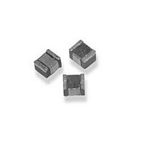
Low Inductance, High Frequency Chip Inductor
Type 3650 Series
Item
Operating Temp. Range:
Humidity Resistance:
Low Temp. Storage Test:
Thermal Shock Test:
High Temp. Storage Test:
High Temp. Load Life Test:
Humidity Load Life:
* Storage Temperature: 25±3°C, <80%RH
36502C
36502A
36501J
36501E
36512C
36512A
36532C
36532A
36521J
Series
Series
Series
Max.
Max.
Max.
2.92
2.29
1.80
1.27
2.92
2.29
2.92
2.29
1.80
A
A
A
Dimensions are in millimetres
unless otherwise specified.
Max.
Max.
Max.
2.79
1.73
1.12
0.76
2.79
1.73
2.79
1.73
1.12
B
B
B
Appearance: No damage
∆L ≤±10%
∆Q ≤±20%
There should be no evidence
of short or open circuit.
Specification
Max.
Max.
Max.
2.10
1.52
1.02
0.61
1.40
1.03
2.03
1.52
1.02
C
C
C
Ref.
0.51
0.51
0.38
0.15
Ref.
0.65
0.51
Ref.
0.65
0.51
0.38
D
D
D
Specifications subject to
change.
2.03
1.27
0.76
0.51
2.03
1.27
2.03
1.27
0.76
E
E
E
Test Method
-40°C to +125°C
Temperature: 40±2°C
Relative Humidity: 90~95%
Time: 96hrs±2hrs
Measured after exposure in the room condition
for 2hrs
Temperature: -40±2°C
Time: 48±2hrs
Inductors are to be tested after 1 hour at
room temperature
One Cycle:
Total: 5 Cycles
Temperature:125±2°C
Time: 48±2hrs
Measured after 1 hour at room temperature
Temperature:85±2°C
Time:1000±12hrs
Load: Rated current
Temperature: 40±2°C
Relative Humidity: 90~95%
Time: 1000±12hrs
Load: Rated current
0.51
0.51
0.33
0.23
0.51
0.44
0.51
0.44
0.33
Step
F
F
F
1
2
3
4
1.52
1.02
0.86
0.56
1.52
1.02
1.52
1.02
0.86
G
G
G
Temperature(°C)
-25±3
25±2
85±3
25±2
www.tycoelectronics.com
passives.tycoelectronics.com
2.54
1.78
1.02
0.66
2.54
1.78
2.54
1.78
1.02
H
H
H
1.02
1.02
0.64
0.50
1.02
1.02
1.02
1.02
0.64
I
I
I
Time (min)
30
15
30
15
1.27
0.76
0.64
0.46
1.27
0.76
1.27
0.76
0.64
J
J
J
Related parts for 36502CR18JTDG
Image
Part Number
Description
Manufacturer
Datasheet
Request
R


Part Number:
Description:
Connector,DIN-41612,PCB Mount,RECEPT,96 Contacts,PIN,0.1 Pitch,R ANGLE PC TAIL Terminal
Manufacturer:
Molex Inc

Part Number:
Description:
Printers THERMAL PRINTER HS-SLEEVE MARKER
Manufacturer:
TE Connectivity


Part Number:
Description:
Manufacturer:
TE Connectivity
Datasheet:


Part Number:
Description:
Manufacturer:
TE Connectivity
Datasheet:

Part Number:
Description:
Manufacturer:
TE Connectivity
Datasheet: