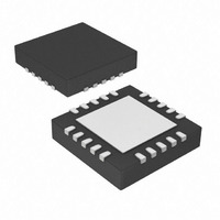
AR1010T-I/ML Microchip Technology, AR1010T-I/ML Datasheet - Page 27

AR1010T-I/ML
Manufacturer Part Number
AR1010T-I/ML
Description
IC TOUCH SCRREN CTRLR 20-QFN
Manufacturer
Microchip Technology
Type
Resistiver
Specifications of AR1010T-I/ML
Package / Case
20-VQFN Exposed Pad, 20-HVQFN, 20-SQFN, 20-DHVQFN
Touch Panel Interface
4-Wire, 5-Wire, 8-Wire
Number Of Inputs/keys
3 Key
Resolution (bits)
10 b
Data Interface
UART
Data Rate/sampling Rate (sps, Bps)
9.6k
Voltage - Supply
3.3 V ~ 5 V
Current - Supply
17mA
Operating Temperature
-40°C ~ 85°C
Mounting Type
Surface Mount
Voltage Supply Source
Single Supply
Supply Voltage Range
3.135V To 3.465V, 4.75V To 5.25V
Operating Temperature Range
-40°C To +85°C
Digital Ic Case Style
QFN
No. Of Pins
20
Svhc
No SVHC (15-Dec-2010)
Supply
RoHS Compliant
Ic Function
Touch Screen Controller
Rohs Compliant
Yes
Lead Free Status / RoHS Status
Lead free / RoHS Compliant
Sampling Rate (per Second)
-
Lead Free Status / RoHS Status
Lead free / RoHS Compliant
Available stocks
Company
Part Number
Manufacturer
Quantity
Price
Company:
Part Number:
AR1010T-I/ML
Manufacturer:
MICROCHIP
Quantity:
12 000
Part Number:
AR1010T-I/ML
Manufacturer:
MICROCHIP/微芯
Quantity:
20 000
7.16 Calibration of Touch Sensor with Controller
The reported coordinates from a touch screen controller are typically calibrated to the application’s video display.
The task is often left up to the host to perform. This controller provides a feature for it to send coordinates that
have already been calibrated, rather than the host needing to perform this task. If enabled, the feature will apply
pre-collected 4-point calibration data to the reported touch coordinates. Calibration only accounts for X and Y
directional scaling. It does not correct for angular errors due to rotation of the touch sensor on the video display.
The calibration process can be cancelled at anytime by sending a command to the controller.
Upon completion of the calibration process, the calibration data is automatically stored to the EEPROM and
“Calibrated Coordinates” is enabled
The process of “calibration” with the controller is described below.
1) Disable touch reporting by issuing <Disable Touch> command.
2) Get register group Start address by issuing <Register Start Address Request> command.
3) Calculate the CalibrationInset register’s address by adding it’s offset value of 0x0E to the register group Start
4) Calculate the desired value for the CalibrationInset register.
5) Set the Calibration Inset by writing the desired value to the CalibrationInset register.
6) Issue the <Calibrate Mode> command.
7) Software to display the first calibration point target in the upper left quadrant of the display and prompt the
8) Wait for the user to touch and release the first calibration point target. Do this by looking for a controller
© 2009 Microchip Technology, Inc.
Send
Receive
A register Start address of 0x07 is used below, for this example.
Send
Receive
address of 0x07.
Register Address = Register Start Address + CalibratioInset Register Offset = 0x07 + 0x0E = 0x15
A Calibration Inset of 12.5% is used below for this example.
CalibrationInset = 2 * Desire Calibration Inset % = 2 * 12.5 = 25 = 0x19
Send
Receive
Send
Receive
user to touch and release the target.
response of: <0x55><0x02><0x00><0x14>
Touch and
release target
: <0x55><0x02><0x00><0x21>
: <0x55><0x02><0x00><0x14>
: <0x55><0x01><0x13>
: <0x55><0x02><Response><0x13>
: <0x55><0x01><0x22>
: <0x55><0x03><0x00><0x22><0x07>
: <0x55><0x05><0x21><0x00><0x15><0x01><0x19>
: <0x55><0x02><0x14><0x04>
DS41393A-Page 23


