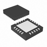
AR1010-I/ML Microchip Technology, AR1010-I/ML Datasheet - Page 16

AR1010-I/ML
Manufacturer Part Number
AR1010-I/ML
Description
IC TOUCH SCREEN CTRLR 20-QFN
Manufacturer
Microchip Technology
Type
Resistiver
Specifications of AR1010-I/ML
Resolution (bits)
10 b
Touch Panel Interface
4-Wire, 5-Wire, 8-Wire
Number Of Inputs/keys
3 Key
Data Interface
UART
Data Rate/sampling Rate (sps, Bps)
9.6k
Voltage - Supply
3.3 V ~ 5 V
Current - Supply
17mA
Operating Temperature
-40°C ~ 85°C
Mounting Type
Surface Mount
Package / Case
20-VQFN Exposed Pad, 20-HVQFN, 20-SQFN, 20-DHVQFN
Voltage Supply Source
Single Supply
Controller Type
Touch Screen
Supply Voltage Range
3.3V To 5V
Operating Temperature Range
-40°C To +85°C
Digital Ic Case Style
QFN
No. Of Pins
20
Interface
UART
Filter Terminals
SMD
Rohs Compliant
Yes
Lead Free Status / RoHS Status
Lead free / RoHS Compliant
Sampling Rate (per Second)
-
Lead Free Status / RoHS Status
Lead free / RoHS Compliant, Lead free / RoHS Compliant
Available stocks
Company
Part Number
Manufacturer
Quantity
Price
Company:
Part Number:
AR1010-I/ML
Manufacturer:
Microchip
Quantity:
1 206
Part Number:
AR1010-I/ML
Manufacturer:
MICROCHIP/微芯
Quantity:
20 000
7.12 Configuration Registers
The Configuration Registers allow application specific customization of the controller. The default values have
been optimized for most applications and are automatically used, unless you choose to change them.
Unique sensors and/or product applications may benefit from adjustment of configuration registers.
The factory default settings for the Configuration registers can be recovered by writing a value of 0xFF to address
0x00 of the EEPROM, then cycling power.
TouchThreshold
SensitivityFilter
SamplingFast
SamplingSlow
AccuracyFilterFast
AccuracyFilterSlow
SpeedThreshold
SleepDelay
PenUpDelay
TouchMode
TouchOptions
CalibrationInset
PenStateReportDelay
TouchReportDelay
Configuration registers are defined as an Offset value from the Start address for the register group.
To read or write to a register, do the following.
1) Issue the <Register Start Address Request> command to obtain the Start address for the register group.
2) Calculated the desired register’s absolute address by adding the register’s Offset value to Start address for
3) Issue the <Register Read> or <Register Write> command, using the calculated register’s absolute address.
7.12.1 TouchThreshold Register (offset 0x02)
The TouchThreshold register sets the threshold for a touch condition to be detected as a touch. A touch is
detected if it is below the TouchThreshold setting. Too small of a value might prevent the controller from
accepting a real touch, while too large of a value might allow the controller to accept very light or false touches
conditions. Valid values are as follows.
0 ≤ TouchThreshold ≤ 255
7.12.2 SensitivityFilter Register (offset 0x03)
The SensitivityFilter register sets the level of touch sensitivity. A higher value is more sensitive to a touch
(accepts a lighter touch), but may exhibit a less stable touch position. A lower value is less sensitive to a touch
(requires a harder touch), but will provide a more stable touch position. Valid values are as follows.
0 ≤ SensitivityFilter ≤ 255
DS41393A-Page 12
Warning: Use of invalid register value will yield unpredictable results!
Register Name
the register group.
Table 8 : Configuration Registers
Address
Offset
0x0C
0x0D
0x0A
0x0B
0x0E
0x0F
0x02
0x03
0x04
0x05
0x06
0x07
0x08
0x11
Value of: 0-255
Value of: 0-255
Value of: 1, 2, 4, 8, 16, 32, 64, 128
Value of: 1, 2, 4, 8, 16, 32, 64, 128
Value of: 1-8
Value of: 1-8
Value of: 0-255
Value of: 0-255
Value of: 0-255
Value of: 0-40
Value of: 0-255
Value of: 0-255
Bit 7
PD2
–
Bit 6
PD1
–
Bit 5
PD0
–
Bit 4
PM1
–
Bit 3
PM0
–
Bit 2
PU2
© 2009 Microchip Technology, Inc.
–
Bit 1
48W
PU1
Bit 0
CCE
PU0
Default
Value
0xC5
0xB1
0xC8
0x04
0x04
0x10
0x02
0x08
0x04
0x64
0x80
0x00
0x19
0x00


