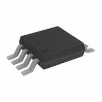
AD7680BRM Analog Devices Inc, AD7680BRM Datasheet - Page 18

AD7680BRM
Manufacturer Part Number
AD7680BRM
Description
IC ADC 16BIT LP UNIPOLAR 8-MSOP
Manufacturer
Analog Devices Inc
Series
PulSAR®r
Datasheet
1.AD7680BRMZ.pdf
(20 pages)
Specifications of AD7680BRM
Rohs Status
RoHS non-compliant
Number Of Bits
16
Sampling Rate (per Second)
100k
Data Interface
DSP, MICROWIRE™, QSPI™, Serial, SPI™
Number Of Converters
1
Power Dissipation (max)
26.4mW
Voltage Supply Source
Single Supply
Operating Temperature
-40°C ~ 85°C
Mounting Type
Surface Mount
Package / Case
8-TSSOP, 8-MSOP (0.118", 3.00mm Width)
Available stocks
Company
Part Number
Manufacturer
Quantity
Price
Part Number:
AD7680BRMZ
Manufacturer:
ADI/亚德诺
Quantity:
20 000
AD7680
It is also possible to take valid data on each SCLK rising edge
rather than falling edge, since the SCLK cycle time is long
enough to ensure the data is ready on the rising edge of SCLK.
However, the first leading zero is still driven by the CS falling
edge, and so it can be taken on only the first SCLK falling edge.
It may be ignored and the first rising edge of SCLK after the CS
falling edge would have the second leading zero provided and
the 23rd rising SCLK edge would have the final trailing zero
provided. This method may not work with most
microcontrollers/DSPs but could possibly be used with FPGAs
and ASICs.
AD7680 TO ADSP-218x
The ADSP-218x family of DSPs can be interfaced directly to the
AD7680 without any glue logic required. The SPORT control
register should be set up as follows:
To implement the power-down mode, SLEN should be set to
0111 to issue an 8-bit SCLK burst. The connection diagram is
shown in Figure 22. The ADSP-218x has the TFS and RFS of the
SPORT tied together, with TFS set as an output and RFS set as
TFSW = RFSW = 1, Alternate Framing
INVRFS = INVTFS = 1, Active Low Frame Signal
DTYPE = 00, Right Justify Data
SLEN = 0111, 8-Bit Data-Words
ISCLK = 1, Internal Serial Clock
TFSR = RFSR = 0, Frame First Word
IRFS = 0
ITFS = 1
Rev. 0 | Page 18 of 20
an input. The DSP operates in alternate framing mode and the
SPORT control register is set up as described. Transmit and
receive autobuffering is used in order to get a 24 SCLK transfer.
Each buffer contains three 8-bit words. The frame synchroniza-
tion signal generated on the TFS is tied to CS , and as with all
signal processing applications, equidistant sampling is necessary.
In this example, the timer interrupt is used to control the
sampling rate of the ADC.
The timer register is loaded with a value that provides an
interrupt at the required sample interval. When an interrupt is
received, the values in the transmit autobuffer start to be
transmitted and TFS is generated. The TFS is used to control
the RFS and therefore the reading of data. The data is stored in
the receive autobuffer for processing or to be shifted later. The
frequency of the serial clock is set in the SCLKDIV register.
When the instruction to transmit with TFS is given, i.e.,
TX0 = AX0, the state of the SCLK is checked. The DSP waits
until the SCLK has gone high, low, and high again before
transmission starts. If the timer and SCLK values are chosen
such that the instruction to transmit occurs on or near the
rising edge of SCLK, the data may be transmitted or it may wait
until the next clock edge.
*ADDITIONAL PINS OMITTED FOR CLARITY
AD7680*
Figure 22. Interfacing to the ADSP-218x
SDATA
SCLK
CS
SCLK
DR
RFS
TFS
ADSP-218x*


