521599-1 TE Connectivity, 521599-1 Datasheet - Page 4
521599-1
Manufacturer Part Number
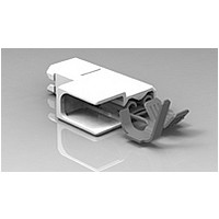
521599-1
Description
187 ULTRA-POD FLAG 18-14 BR
Manufacturer
TE Connectivity
Specifications of 521599-1
Proprietary Name
Ultra-Pod
Receptacle Style
Flag
Mating Area Interface Dimensions (mm [in])
4.75 x 0.81 [.187 x .032]
Insulation Diameter (mm [in])
2.79-3.81 [.110-.150]
Insertion Force
Normal
Finish
None
Insulation Support
Insulation Support
Color
Natural
Fully Insulated
Yes
Wire Range (mm [awg])
0.80-2.00² [18-14], (2) 0.80-0.90² [(2) 18]
Ul Flammability Rating
UL 94V-2
Housing Material
Nylon 6/6
Rohs/elv Compliance
RoHS compliant, ELV compliant
Lead Free Solder Processes
Not relevant for lead free process
Rohs/elv Compliance History
Always was RoHS compliant
Packaging Method
Strip


3.6.
4.
4.1.
Rev A
Examination of product
Low level contact resistance
Withstanding voltage, Test Condition A
Withstanding voltage, Test Condition C
Withstanding voltage, receptacle, tab entry position
Temperature rise vs current
Current cycling
Crimp tensile
Durability
Contact retention
Engagement/disengagement force
Humidity-temperature cycling
Temperature life
Heat age
Product Qualification and Requalification Test Sequence
QUALITY ASSURANCE PROVISIONS
Qualification Testing
A.
B.
NOTE
Specimen Selection
Specimens shall be prepared in accordance with applicable Instruction Sheets and shall be
selected at random from current production. Test group 1 shall consist of 20 specimens of the
maximum and minimum wire size and terminal type. Test group 2 shall consist of 20 specimens
of each wire size and terminal type. Test groups 3, 4, 5, 6 and 7 shall each consist of 20
specimens of each terminal type. Test group 8 shall consist of 20 specimens of each terminal
type per group on the maximum wire size for the intended range of wires. All terminated
specimens shall be crimped to the appropriate tin plated test conductors.
Test Sequence
Qualification inspection shall be verified by testing specimens as specified in Figure 2.
(a) See paragraph 4.1.A.
(b) Numbers indicate sequence in which tests are performed.
(c) Temperature rise and voltage drop measurements during current cycling are to be
Test or Examination
collected simultaneously. Prepare samples in accordance with UL 310.
Figure 2
2,4(c)
3(c)
1,5
1
1,4
2
2
3
1,4
3
3
2
Test Sequence (b)
Test Group (a)
1,3
4
2
1,3
5
2
1,3
6
2
1,3
7
2
108-2215
1,9
2,7
3,8
8
4
6
5
4 of 6
Related parts for 521599-1
Image
Part Number
Description
Manufacturer
Datasheet
Request
R

Part Number:
Description:
187 ULTRA-POD FLAG 18-14 TPBR
Manufacturer:
TE Connectivity
Datasheet:

Part Number:
Description:
Printers THERMAL PRINTER HS-SLEEVE MARKER
Manufacturer:
TE Connectivity


Part Number:
Description:
High Speed / Modular Connectors 30P HEADER ASSY
Manufacturer:
TE Connectivity
Datasheet:

Part Number:
Description:
High Speed / Modular Connectors REC 6X005P R/A LT B-PLANE HS3
Manufacturer:
TE Connectivity
Datasheet:

Part Number:
Description:
High Speed / Modular Connectors 2MM HM RCPT 50P R/A AU
Manufacturer:
TE Connectivity
Datasheet:

Part Number:
Description:
High Speed / Modular Connectors 2MM HM RCPT 50P R/A AU
Manufacturer:
TE Connectivity
Datasheet:


Part Number:
Description:
Manufacturer:
TE Connectivity
Datasheet:


Part Number:
Description:
Manufacturer:
TE Connectivity
Datasheet:

Part Number:
Description:
Manufacturer:
TE Connectivity
Datasheet:

Part Number:
Description:
Manufacturer:
TE Connectivity
Datasheet: