5-6605450-8 TE Connectivity, 5-6605450-8 Datasheet - Page 2
5-6605450-8
Manufacturer Part Number
5-6605450-8
Description
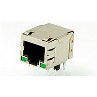
1X1 MAG45(TM) 10/100 426P1 G/Y
Manufacturer
TE Connectivity
Specifications of 5-6605450-8
Rohs Compliant
YES
Product Type
Connector
Number Of Cores
4
Magnetics
Integrated Magnetics
Jack Type
RJ45
Signal Routing Type
Auto MDI/MDIX
Profile
Standard
Pcb Mounting Orientation
Side Entry (Right Angle)
Jack Configuration
1 x 1
Turns Ratio
1:1
Shielded
Yes
Emi Finger - Bottom
Without
Termination Method
Solder
Port Configuration
Single
Emi Fingers -top And Sides
With
Latch Orientation
Standard - Latch Down
Pcb Tail Length (mm [in])
4.32 [0.170]
Contact Termination Type
Through Hole
Preloaded
Yes
Connector Style
Jack
Status Indicator
LED
Decoupling Capacitor
2KV
Rear Pcb Ground Tab
Without
Signal Lead Quantity
8
Rohs/elv Compliance
RoHS compliant, ELV compliant
Lead Free Solder Processes
Wave solder capable to 240°C, Wave solder capable to 260°C, Wave solder capable to 265°C
Rohs/elv Compliance History
Always was RoHS compliant
Left Led Color (position #1)
Green
Right Led Color (position #2)
Yellow
Operating Temperature (°c [°f])
0 – 70 [32 – 158]
Applies To
Printed Circuit Board
Environmental Conditions
Office / Premises
Application
10/100BASE-T Ethernet


3.4.
3.5.
3.6.
Examination of product.
Dry circuit resistance.
Open circuit inductance.
Random vibration, operational.
Random vibration, non-operational.
Rev D
●
Product Codes
Product Codes for this product family are H363, H364, H365 and H366
Performance and Test Description
Product is designed to meet the electrical, mechanical and environmental performance requirements
specified in Figure 1. Unless otherwise specified, all tests shall be performed at ambient environmental
conditions per EIA-364.
Test Requirements and Procedures Summary
Test Description
Temperature:
•
•
Standard: 0 to 70° C |
Extended temperature varieties: -40 to 85° C
Meet requirements of product
drawing, and dimensional and
plating requirements of FCC Part
68, Subpart F, Connector
Specification per Figure
68.500(d)(2)(i) 8 Position Series
Modular Jack.
See Engineering Report 502-1129.
OCL 350 µH minimum.
No discontinuities of 1
microsecond
or longer duration.
See Note.
See Note.
R 30 milliohms maximum.
Figure 1 (continued)
MECHANICAL
ELECTRICAL
Requirement
Measure per drawing, inspect
plating thickness per x-ray
evaluation per EIA-364-48 Method
C.
EIA-364-23A.
Subject specimens to 100 mA
maximum and 20 mV maximum
open circuit voltage.
See Figure 3.
ANSI X3.263, ref IEEE 802.3.
Measure and record mutual
inductance of mated and mounted
specimens at 100 kHz, 100 mV, 8
mA DC bias, and 25° C.
EIA-364-28D,
Test Condition VIIA.
Subject specimens to 1.0 G rms
between 3-500 Hz. PSD of .003.
45 minutes in each of 3 mutually
perpendicular planes.
EIA-364-28D,
Test Condition VIIA.
Subject specimens to 1.0 G rms
between 3-500 Hz. PSD of .003.
45 minutes in each of 3 mutually
perpendicular planes.
Procedure
108-2100
2 of 6
Related parts for 5-6605450-8
Image
Part Number
Description
Manufacturer
Datasheet
Request
R

Part Number:
Description:
CONN HOUSING 66POS .100 POL DUAL
Manufacturer:
Tyco Electronics
Datasheet:

Part Number:
Description:
TRIMMER-1/2" SQ MT WW
Manufacturer:
Bourns Inc.
Datasheet:

Part Number:
Description:
1X5 MAG45(TM) 7H2,66,CAP,G/Y R
Manufacturer:
TE Connectivity
Datasheet:

Part Number:
Description:
Manufacturer:
TE Connectivity
Datasheet:

Part Number:
Description:
1X8 MAG45 7K1, 66, G/Y RLED, C
Manufacturer:
TE Connectivity
Datasheet:

Part Number:
Description:
187 FASTON REC.IS
Manufacturer:
TE Connectivity
Datasheet:

Part Number:
Description:
Conn Shrouded Header HDR 7 POS 2.54mm Solder ST Thru-Hole Tube
Manufacturer:
TE Connectivity
Datasheet:

Part Number:
Description:
Conn Shrouded Header HDR 40 POS 1.27mm Solder RA Thru-Hole Tube
Manufacturer:
TE Connectivity
Datasheet:

Part Number:
Description:
Manufacturer:
TE Connectivity
Datasheet:

Part Number:
Description:
Manufacturer:
TE Connectivity
Datasheet:

Part Number:
Description:
.050CL,CHAMP,VERT PLUG,50 POSN
Manufacturer:
TE Connectivity
Datasheet:

Part Number:
Description:
Conn Shrouded Header HDR 16 POS 2.54mm Solder ST Thru-Hole
Manufacturer:
TE Connectivity
Datasheet:

Part Number:
Description:
0.8FH,R09H.5,140,08/SN,TU
Manufacturer:
TE Connectivity
Datasheet:

Part Number:
Description:
STRAIN RELIEF, BLACK, RG59
Manufacturer:
TE Connectivity
Datasheet:

Part Number:
Description:
SOCKET, VERTICAL, 0.8MM, 13MM, 140WAY
Manufacturer:
TE Connectivity
Datasheet: