5-640470-4 TE Connectivity, 5-640470-4 Datasheet
5-640470-4
Specifications of 5-640470-4


Related parts for 5-640470-4


5-640470-4 Summary of contents
Page 1
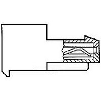
... This specification covers performance, tests and quality requirements for the TE Connectivity (TE) MTA-100 connector system. This system is mass terminated using insulation displacement technology on .100 inch centerlines and mates with .025 inch square posts providing a reliable interconnection between wires and posts mounted on printed circuit boards. The standard system is available in 2 through 28 positions ...
Page 2
... Figure 1 (cont) 108-1050 Procedure Visual, dimensional and functional per applicable quality inspection plan. TE 109-6-1. Subject mated contacts assembled in housing maximum open circuit at 100 ma maximum. See Figures 3 and 5. TE Spec 109-28-4. Test between adjacent contacts of unmated samples. TE Spec 109-29-1. Test between adjacent contacts of unmated samples ...
Page 3
... TE Spec 109-42, Condition A. Measure force necessary to mate samples with friction lock header from point of initial contact to depth of .200 inch at maximum rate of .5 inch per minute. TE Spec 109-42, Condition A. Measure force necessary to unmate samples from friction lock header at maximum rate of .5 inch per minute. ...
Page 4
... Tin-lead plated samples. (d) Gold plated samples. (e) Discontinuities shall not be measured. Energize at 18 Test Specification 109-151. (f) Subject half the samples to the parallel tensile test and the remaining half to the perpendicular tensile test. (g) Precondition samples with 5 cycles durability. Rev H Test Group (a) 1 2(c) 3(d) 4 ...
Page 5
... PN 93-660652; and 3, 10 position standard tin-lead plated samples terminated to 22 AWG wire and mounted on printed circuit board PN 93-660651 (see Figure 5). Test group 3 shall consist position gold plated samples terminated to 22 AWG wire and mounted on printed circuit board PN 93-660017. Test group 4 shall consist of 5 unmounted 24 position standard tin-lead plated samples terminated to the maximum wire size ...
Page 6
... Termination resistance equals millivolts divided by test current less resistance of 2 NOTE inches of wire. (b) After wave soldering, the boards and posts shall be cleaned to remove all flux and contaminates. Temperature & Termination Resistance Measurement Points Rev H Figure 3 108-1050 ...
Page 7
... NOTE gage indicated, use the Multiplication Factor (F) from the above chart and multiply it times the Base Rated Current for a single circuit at maximum ambient operating temperature as shown in Figure 4A. Rev H Figure 4A Current Carrying Capability Wire Size AWG 100 .3 .4 Figure 4B Current Rating 108-1050 1 ...
Page 8
... PC Board Used For Termination Resistance Dry Circuit Rev H PC Board Used For Current Rating Figure 5 Printed Circuit Test Boards 108-1050 ...
Page 9
... Rev H Figure 6 Termination Tensile Strength 108-1050 ...