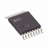
MAX1154BEUE+ Maxim Integrated Products, MAX1154BEUE+ Datasheet - Page 13

MAX1154BEUE+
Manufacturer Part Number
MAX1154BEUE+
Description
IC ADC 10BIT SYS MON 16TSSOP
Manufacturer
Maxim Integrated Products
Datasheet
1.MAX1153BEUE.pdf
(30 pages)
Specifications of MAX1154BEUE+
Number Of Bits
10
Sampling Rate (per Second)
94k
Data Interface
MICROWIRE™, QSPI™, Serial, SPI™
Number Of Converters
1
Power Dissipation (max)
15mW
Voltage Supply Source
Single Supply
Operating Temperature
-40°C ~ 85°C
Mounting Type
Surface Mount
Package / Case
16-TSSOP
Number Of Adc Inputs
10
Architecture
SAR
Conversion Rate
94 KSPs
Resolution
10 bit
Interface Type
Serial
Voltage Reference
Internal 4.096 V or External
Supply Voltage (max)
5 V
Mounting Style
SMD/SMT
Lead Free Status / RoHS Status
Lead free / RoHS Compliant
In differential mode, the T/H samples the difference
between two analog inputs, eliminating common-mode
DC offsets and noise. See the Input Configuration
Register section and Tables 5 and 6 for more details on
configuring the analog inputs.
When performing differential conversions, the input
configuration register (Tables 5 and 6) also selects
between unipolar and bipolar operation. Unipolar mode
sets the differential input range from 0 to V
tive differential analog input in unipolar mode causes
the digital output code to be zero. Selecting bipolar
mode sets the differential input range to ±V
digital output code is straight binary in unipolar mode
and two’s complement in bipolar mode (see the
Transfer Function section).
In single-ended mode, the MAX1153/MAX1154 always
operate in unipolar mode. The analog inputs are inter-
nally referenced to GND with a full-scale input range
from 0 to V
Figure 5. Single-Ended/Differential Input Equivalent Input Circuit
SPI and QSPI are trademarks of Motorola, Inc.
MICROWIRE is a trademark of National Semiconductor Corp.
with Internal Temperature Sensor and V
Stand-Alone, 10-Channel, 10-Bit System Monitors
DIFFERENTIAL
DIFFERENTIAL INPUT EQUIVALENT INPUT CIRCUIT
8-TO-1
TEMP
MUX
V
REF.
DD
______________________________________________________________________________________
H
T
T
CHOLDN
H
CHOLDP
T
V
AZ
T
Unipolar/Bipolar
H
REF.
REF
ADC
A nega-
/2. The
The MAX1153/MAX1154 digital interface consists of
five signals: CS, SCLK, DIN, DOUT, and INT. CS,
SCLK, DIN, and DOUT comprise an SPI™-compatible
serial interface (see the Serial Digital Interface section) .
INT is an independent output that provides an indica-
tion that an alarm has occurred in the system (see the
INT Interrupt Output section).
The MAX1153/MAX1154 feature a serial interface com-
patible with SPI, QSPI™, and MICROWIRE™ devices.
For SPI/QSPI, ensure that the CPU serial interface runs
in master mode so it generates the serial clock signal.
Select a serial clock frequency of 10MHz or less, and
set clock polarity (CPOL) and phase (CPHA) in the µP
control registers to the same value, one or zero. The
MAX1153/MAX1154 support operation with SCLK idling
high or low, and thus operate with CPOL = CPHA = 0 or
CPOL = CPHA = 1.
DIFFERENTIAL
SINGLE-ENDED INPUT EQUIVALENT INPUT CIRCUIT
8-TO-1
TEMP
MUX
V
DD
H
T
CHOLD
Serial Digital Interface
Digital Interface
DD
T
V
AZ
Monitor
H
ADC
13


