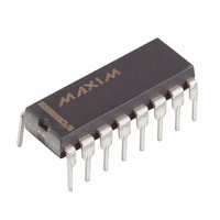
DS1615 Maxim Integrated Products, DS1615 Datasheet - Page 17

DS1615
Manufacturer Part Number
DS1615
Description
IC RECORDER TEMP 5V 16-DIP
Manufacturer
Maxim Integrated Products
Type
Temperature Recorderr
Datasheet
1.DS1615.pdf
(24 pages)
Specifications of DS1615
Memory Size
32B
Time Format
HH:MM:SS (12/24 hr)
Date Format
YY-MM-DD-dd
Interface
3-Wire Serial
Voltage - Supply
4 V ~ 5.5 V
Operating Temperature
-40°C ~ 85°C
Mounting Type
Through Hole
Package / Case
16-DIP (0.300", 7.62mm)
Lead Free Status / RoHS Status
Contains lead / RoHS non-compliant
Available stocks
Company
Part Number
Manufacturer
Quantity
Price
Part Number:
DS1615S
Manufacturer:
MAXIM/美信
Quantity:
20 000
DS1615
Synchronous Communication
Synchronous communication is accomplished over the 3-wire bus which is composed of three signals.
These are the
(reset), the SCLK (serial clock), and I/O (data I/O) pins. The 3-wire bus operates at a
RST
maximum data rate of 2 Mbps. All data transfers are initiated by driving the
input high and are
RST
terminated by driving
low. (See Figures 6 and 7.) A clock cycle is a sequence of a falling edge
RST
followed by a rising edge. For data inputs, the data must be valid during the rising edge. Data bits are
output on the falling edge of the clock and remain valid through the rising edge.
When reading data from the DS1615, the I/O pin goes to a high impedance state when the clock is high.
Taking
low will terminate any communication and cause the I/O pin to go to a high impedance state.
RST
General Communications Format
Communication with the DS1615 in both synchronous and asynchronous modes is accomplished by first
writing a command to the device. The command is then followed by the parameters and/or data required
by the command. The command set for the DS1615 can be seen in Table 3. Reads and writes to the
DS1615 differ in that writes are performed one byte at a time while reads are performed in page long (up
to 32 byte) bursts. Writing one byte at a time means that a write command has to be issued before each
byte of data that is written. For example, writing to the user NV RAM requires that the Write User NV
RAM command be writ-ten followed by the address to be written and then the actual data byte. Writing a
second data byte would require the same procedure with a new address specified. Reads, however, are
accomplished in bursts. For example, if an end user wants to read data from a specific page he would
first issue the Read Page command, followed by the address to begin reading. After the DS1615 receives
the command and starting address, it will immediately transmit the data that resides at the given address
location. However, rather than stop with that single byte of data, the DS1615 will continue transmitting
the next byte of data and will continue transmitting data until the page boundary is reached. A page read
can begin at any address, but will always end at the page boundary. Thus, a page read can range from 1
to 32 bytes. It should be noted that a read can be terminated at any time when communicating in
synchronous mode by pulling
to ground. However, in asynchronous mode, the DS1615 will not
RST
stop transmitting data until the page boundary is reached.
Cyclical Redundancy Check (CRC)
When communicating in the asynchronous mode, a 16-bit CRC is transmitted by the DS1615 following
the transmission of all data. When communicating in synchronous mode, no CRC is transmitted.
The 16-bit CRC (Cyclical Redundancy Check) is used to insure the accuracy of the data that is read from
16
15
the DS1615. The CRC is generated according to the standardized CRC16-polynomial function X
+ X
+
2
X
1. Figure 4 illustrates the function of the generator. The CRC is generated by clearing the CRC
generator and then shifting in data from the register set being read. A sixteen bit CRC is transmitted by
the DS1615 after the last register of any page of memory is read. In other words, a CRC is generated at
the end boundary of every page that is read.
17 of 24


