2-641215-0 TE Connectivity, 2-641215-0 Datasheet
2-641215-0
Specifications of 2-641215-0


Related parts for 2-641215-0


2-641215-0 Summary of contents
Page 1
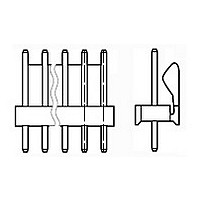
... This specification covers performance, tests and quality requirements for the TE Connectivity (TE) .100 inch centerline Crimp-Snap connectors. The Crimp-Snap Terminal .100 product is a wire-to-board connection consisting of crimp-snap contacts seated in a housing that mates to .025 inch square post headers on .100 inch centerline and is designed to be terminated AWG wire. 1.2. Qualification When tests are performed on the subject product line, procedures specified in Figure 1 shall be used ...
Page 2
... Ratings ! Voltage: 250 volts AC ! Current: See Figure 4 for applicable current carrying capability ! Temperature: -55 to 105° C 3.4. Performance and Test Description Product is designed to meet the electrical, mechanical and environmental performance requirements specified in Figure 1. Unless otherwise specified, all tests shall be performed at ambient environmental conditions per Test Specification 109-1 ...
Page 3
... Crimp tensile. Thermal shock. Humidity/temperature cycling. Temperature life. Mixed flowing gas. Shall meet visual requirements, show no physical damage and shall meet requirements of NOTE additional tests as specified in Test Sequence in Figure 2. Rev C Requirement No discontinuities of 1 microsecond or longer duration. See Note. See Note. Two pounds maximum per contact. TE Spec 109-42, Condition A. ...
Page 4
... Numbers indicate sequence in which tests are performed. (c) Discontinuities shall not be measured. Energize at 18 Test Specification 109-151. (d) Precondition specimens with 10 cycles durability. Rev C Test Group ( Test Sequence (b) 1,9 1,9 1,7 1,5 1,3 3,7 2,7 2,4 2,5 3 level for 100% loadings per Figure 2 108-1328 6 1 ...
Page 5
... Test groups and 4 shall each consist of a minimum of 5 connector assemblies with a minimum of 30 data points. Test group 5 shall consist of a minimum of 5 headers with a minimum of 30 header posts. Test group 6 shall consist of 25 specimens of each wire size. Specimens for additional testing in test group 1 shall consist of 24, 6 position assemblies with the following plating configurations for CST-100 contact to header: 30 µ ...
Page 6
... Rev C Figure 3 Termination Resistance Measurement Points 108-1328 ...
Page 7
... Percent Connector Loading (20 position connector) To determine the acceptable current carrying capacity for the percentage connector NOTE loading and wire gage indicated, use the Multiplication Factor (F) from the above chart and multiply it times the Base rated Current for a single circuit at maximum ambient operating temperature as shown in Figure 4A ...
Page 8
... Rev C Figure 5 Vibration & Physical Shock Mounting Fixture 108-1328 ...