2-583861-5 TE Connectivity, 2-583861-5 Datasheet
2-583861-5
Specifications of 2-583861-5


Related parts for 2-583861-5


2-583861-5 Summary of contents
Page 1
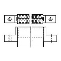
... This specification covers the performance, tests and quality requirements for Crimp Snap Twin Leaf Connector assemblies, used to provide a connection method between discrete wiring and printed circuit boards. Contacts are crimp type, wrap in design. These multi-contact connectors have .100, .125 and .156 inch centerline spacing between adjacent contacts. ...
Page 2
... Test Specification 109-29-1. Test between adjacent contacts of unmated connector assembly; Test Specification 109-28-4, 500 vdc. Subject mated contacts to 50 cycles at 125% rated current for 30 minutes "ON" minutes "OFF"; Test Specification 109-51, cond B, test method 3. Measure potential drop across crimped contacts between wire as ...
Page 3
... Determine crimp tensile at a rate of 1inch/ minute; Test Specification 109-16. Mate and unmate connector assemblies with 30 microinches gold for 250 cycles with gage 1. see Figure 7; Test Specification Spec 109-27. Subject mated connectors to 5 cycles between -55° and 105° C; Test Specification 109-22. ...
Page 4
... Sheets. They shall be selected at random from current production. Test samples shall consist of six connectors of the greatest number of positions of each connector type offered, three each test group 1 and test group 2. Two additional specimens shall be selected from the least number of positions offered and tested to group 2. When connectors are mated, use PC boards as illustrated in Figure 4 ...
Page 5
... Dimensional and functional requirements shall be in accordance with the applicable product drawing and this specification. Altitude feet Sea Level 50,000 70,000 5 ma maximum leakage No breakdown or flashover Rev D Test Voltage, rms .100 cl .125 cl .156 cl 1000 1500 1800 400 525 675 280 375 450 ...
Page 6
... The test card shall extend 4.00 +/-.02 from the receptacle after insertion. 4. Number of contacts shall be the same as on the corresponding printed wiring board. 5. Printed circuit test board shall be 2 ounces copper and gold over nickel plated per MIL-STD-275. 6. This dimension shall be the minimum connector card slot length minus .008. ...
Page 7
Rev D Figure 5 Termination Resistance Test Circuit Figure 6 Crimp Resistance 108-9031 ...
Page 8
... Tolerances: +/-.005 unless otherwise indicated. NOTES 2. Material: Tool steel, hardened to Rockwell C50-55. 3. Gage surface shall be clean of contaminants or lubricants. Rev D Gage A B Number 1 .0700 (a) 2 .0540 (a) Figure 7 Printed Board Simulator 108-9031 ...