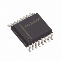
DS3231SN# Maxim Integrated Products, DS3231SN# Datasheet - Page 9

DS3231SN#
Manufacturer Part Number
DS3231SN#
Description
IC RTC W/TCXO 16-SOIC
Manufacturer
Maxim Integrated Products
Type
Clock/Calendar/TCXO/Crystalr
Datasheet
1.DS3231S.pdf
(20 pages)
Specifications of DS3231SN#
Time Format
HH:MM:SS (12/24 hr)
Date Format
YY-MM-DD-dd
Interface
I²C, 2-Wire Serial
Voltage - Supply
2.3 V ~ 5.5 V
Operating Temperature
-40°C ~ 85°C
Mounting Type
Surface Mount
Package / Case
16-SOIC (0.300", 7.5mm Width)
Function
Clock/Calendar/Battery Backup
Supply Voltage (max)
5.5 V
Supply Voltage (min)
2.3 V
Maximum Operating Temperature
+ 85 C
Minimum Operating Temperature
- 40 C
Mounting Style
SMD/SMT
Rtc Bus Interface
Serial (I2C)
Lead Free Status / RoHS Status
Lead free / RoHS Compliant
Memory Size
-
Lead Free Status / Rohs Status
Lead free / RoHS Compliant
Available stocks
Company
Part Number
Manufacturer
Quantity
Price
The DS3231 is a serial RTC driven by a temperature-
compensated 32kHz crystal oscillator. The TCXO pro-
vides a stable and accurate reference clock, and
maintains the RTC to within ±2 minutes per year accu-
racy from -40°C to +85°C. The TCXO frequency output
is available at the 32kHz pin. The RTC is a low-power
clock/calendar with two programmable time-of-day
alarms and a programmable square-wave output. The
INT/SQW provides either an interrupt signal due to
alarm conditions or a square-wave output. The clock/cal-
endar provides seconds, minutes, hours, day, date,
month, and year information. The date at the end of the
month is automatically adjusted for months with fewer
than 31 days, including corrections for leap year. The
5–12
PIN
13
14
15
16
1
2
3
4
NAME
32kHz
GND
V
N.C.
SDA
V
SCL
/SQW
BAT
CC
32kHz Output. This open-drain pin requires an external pullup resistor. When enabled, the output operates
on either power supply. It may be left open if not used.
DC Power Pin for Primary Power Supply. This pin should be decoupled using a 0.1μF to 1.0μF capacitor.
If not used, connect to ground.
Active-Low Interrupt or Square-Wave Output. This open-drain pin requires an external pullup resistor
connected to a supply at 5.5V or less. This multifunction pin is determined by the state of the INTCN bit in
the Control Register (0Eh). When INTCN is set to logic 0, this pin outputs a square wave and its frequency
is determined by RS2 and RS1 bits. When INTCN is set to logic 1, then a match between the timekeeping
registers and either of the alarm registers activates the
INTCN bit is set to logic 1 when power is first applied, the pin defaults to an interrupt output with alarms
disabled. The pullup voltage can be up to 5.5V, regardless of the voltage on V
be left unconnected.
Active-Low Reset. This pin is an open-drain input/output. It indicates the status of V
V
pin is pulled high by the internal pullup resistor. The active-low, open-drain output is combined with a
debounced pushbutton input function. This pin can be activated by a pushbutton reset request. It has an
internal 50k
oscillator is disabled, t
No Connection. Must be connected to ground.
Ground
Backup Power-Supply Input. When using the device with the V
pin should be decoupled using a 0.1μF to 1.0μF low-leakage capacitor. When using the device with the
V
The device is UL recognized to ensure against reverse charging when used with a primary lithium battery.
Go to www.maxim-ic.com/qa/info/ul.
Serial Data Input/Output. This pin is the data input/output for the I
requires an external pullup resistor. The pullup voltage can be up to 5.5V, regardless of the voltage on V
Serial Clock Input. This pin is the clock input for the I
movement on the serial interface. Up to 5.5V can be used for this pin, regardless of the voltage on V
PF
BAT
specification. As V
Detailed Description
input as the backup power source, the capacitor is not required. If V
nominal value pullup resistor to V
Extremely Accurate I
_____________________________________________________________________
CC
REC
falls below V
is bypassed and
PF
, the
clock operates in either the 24-hour or 12-hour format
with an AM/PM indicator. The internal registers are
accessible though an I
A temperature-compensated voltage reference and
comparator circuit monitors the level of V
power failures and to automatically switch to the back-
up supply when necessary. The RST pin provides an
external pushbutton function and acts as an indicator
of a power-fail event.
The block diagram shows the main elements of the
DS3231. The eight blocks can be grouped into four
functional groups: TCXO, power control, pushbutton
function, and RTC. Their operations are described sep-
arately in the following sections.
CC
FUNCTION
immediately goes high.
. No external pullup resistors should be connected. If the
pin is driven low. When V
2
C serial interface and is used to synchronize data
/SQW pin (if the alarm is enabled). Because the
RTC/TCXO/Crystal
BAT
2
C serial interface. This open-drain pin
input as the primary power source, this
2
2
BAT
C bus interface.
CC
C-Integrated
is not used, connect to ground.
CC
exceeds V
. If not used, this pin can
Pin Description
CC
relative to the
PF
Operation
, for t
CC
RST
to detect
, the
CC
.
CC
.
9


