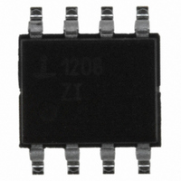
ISL1208IB8Z Intersil, ISL1208IB8Z Datasheet - Page 20

ISL1208IB8Z
Manufacturer Part Number
ISL1208IB8Z
Description
IC RTC LP BATT BACKED SRAM 8SOIC
Manufacturer
Intersil
Type
Clock/Calendar/NVSRAMr
Datasheet
1.ISL1208IB8Z-TK.pdf
(24 pages)
Specifications of ISL1208IB8Z
Memory Size
2B
Time Format
HH:MM:SS (12/24 hr)
Date Format
YY-MM-DD-dd
Interface
I²C, 2-Wire Serial
Voltage - Supply
2.7 V ~ 5.5 V
Operating Temperature
-40°C ~ 85°C
Mounting Type
Surface Mount
Package / Case
8-SOIC (3.9mm Width)
Lead Free Status / RoHS Status
Lead free / RoHS Compliant
Available stocks
Company
Part Number
Manufacturer
Quantity
Price
Company:
Part Number:
ISL1208IB8Z
Manufacturer:
Intersil
Quantity:
5 300
Part Number:
ISL1208IB8Z
Manufacturer:
INTERSIL
Quantity:
20 000
Company:
Part Number:
ISL1208IB8Z-TK
Manufacturer:
STC
Quantity:
1 000
Part Number:
ISL1208IB8Z-TK
Manufacturer:
INTERSIL
Quantity:
20 000
Another consideration is systems with either ground bounce
or power supply transients that cause the V
below ground for more than a few nanoseconds. This type of
power glitch can override the V
corrupt the SRAM. If these transient glitches are present in a
system with the ISL1208, or the device is experiencing
unexplained loss of data when returning from V
protection circuit should be added. Figure 20 shows a circuit
which effectively isolates the V
glitches. The Schottky diode is needed to for low voltage
drop and effective protection from the negative transient.
Note that this circuit will also help if the V
than 50us as CIN holds up the V
There is also a shunt shown between the battery and the
V
where a transient has latched the device and it will not
communicate on the I2C bus. If ground bounce is a problem,
then a second Schottky diode should be added between the
battery and the V
Super Capacitor Backup
A Super Capacitor can be used as an alternative to a battery
in cases where shorter backup times are required. Since the
battery backup supply current required by the ISL1208 is
extremely low, it is possible to get months of backup
operation using a Super Capacitor. Typical capacitor values
are a few µF to 1F or more depending on the application.
If backup is only needed for a few minutes, then a small
inexpensive electrolytic capacitor can be used. For extended
periods, a low leakage, high capacity Super Capacitor is the
best choice. These devices are available from such vendors
as Panasonic and Murata. The main specifications include
working voltage and leakage current. If the application is for
charging the capacitor from a +5V ±5% supply with a signal
diode, then the voltage on the capacitor can vary from ~4.5V
to slightly over 5.0V. A capacitor with a rated WV of 5.0V
may have a reduced lifetime if the supply voltage is slightly
high. The leakage current should be as small as possible.
For example, a Super Capacitor should be specified with
leakage of well below 1µA. A standard electrolytic capacitor
with DC leakage current in the microamps will have a
severely shortened backup time.
D
2.7V TO 5.5V
BAT
FIGURE 20. POWER GLITCH PROTECTION CIRCUIT
IN
pin. This is for quick disconnect if there is a situation
0.1µF
C
IN
BAT54
V
DD
BAT
ISL1208
GND
pin.
V
BAT
20
DD
BAT
DD
input from negative
backup and reset or
SHUNT
pin during the transient.
DD
DD
fall time is less
C
0.1µF
pin to drop
BAT
BAT
mode, a
+
BT1
3.0V
3.6V
TO
ISL1208
Below are some examples with equations to assist with
calculating backup times and required capacitance for the
ISL1208 device. The backup supply current plays a major
part in these equations, and a typical value was chosen for
example purposes. For a robust design, a margin of 30%
should be included to cover supply current and capacitance
tolerances over the results of the calculations. Even more
margin should be included if periods of very warm
temperature operation are expected.
Example 1. Calculating Backup Time Given
Voltages and Capacitor Value
In Figure 21, use C
V
diode turns off completely. The ISL1208 is specified to
operate down to V
charge/discharge equation (Equation 4) is used to estimate
the total backup time:
Rearranging gives:
C
voltage from fully charged to loss of operation. Note that
I
plus the leakage current of the capacitor and the diode, I
In these calculations, I
and will be ignored. If an application requires extended
operation at temperatures over +50°C, these leakages will
increase and hence reduce backup time.
Note that I
Typical Performance Curves on page 7). This allows us to
make an approximation of I
between the two endpoints. The typical linear equation for
I
Using this equation to solve for the average current given 2
voltage points gives Equation 7:
dT = C
I
I = C
TOT
BAT
I
BAT
BATAVG
CC
BAT
FIGURE 21. SUPERCAPACITOR CHARGING CIRCUIT
= 5.0V, the voltage at V
vs V
2.7V TO 5.5V
BAT
is the total of the supply current of the ISL1208 (I
= 1.031E-7*(V
is the backup capacitance and dV is the change in
BAT
BAT
= 5.155E-8*(V
* dV/dT
BAT
* dV/I
is in Equation 6:
changes with V
TOT
BAT
BAT
BAT
to solve for backup time.
LKG
= 1.8V. The capacitance
) + 1.036E-7 Amps
= 0.47F and V
V
BAT2
DD
is assumed to be extremely small
BAT
BAT
1N4148
+ V
GND
BAT
, using a value midway
will approach 4.7V as the
BAT1
V
almost linearly (see
BAT
) + 1.036E-7 Amps
CC
= 5.0V. With
September 12, 2008
C
BAT
(EQ. 4)
(EQ. 5)
(EQ. 6)
FN8085.8
(EQ. 7)
BAT
LKG
)
.


