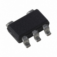
MIC1555BM5 TR Micrel Inc, MIC1555BM5 TR Datasheet - Page 8

MIC1555BM5 TR
Manufacturer Part Number
MIC1555BM5 TR
Description
IC RC TIMER/OSCILLATOR SOT23-5
Manufacturer
Micrel Inc
Type
555 Type, Timer/Oscillator (Single)r
Series
IttyBitty®r
Datasheet
1.MIC1557YM5_TR.pdf
(10 pages)
Specifications of MIC1555BM5 TR
Frequency
5MHz
Voltage - Supply
2.7 V ~ 18 V
Current - Supply
350µA
Operating Temperature
-40°C ~ 85°C
Package / Case
SOT-23-5, SC-74A, SOT-25
# Internal Timers
1
Operating Supply Voltage (min)
2.7V
Operating Supply Voltage (typ)
3.3/5/9/12/15V
Operating Supply Voltage (max)
18V
Package Type
SOT-23
High Level Output Current
-20mA
Low Level Output Current
20mA
Pin Count
5
Operating Temp Range
-40C to 85C
Operating Temperature Classification
Industrial
Mounting
Surface Mount
Lead Free Status / RoHS Status
Contains lead / RoHS non-compliant
Count
-
Lead Free Status / RoHS Status
Not Compliant, Contains lead / RoHS non-compliant
Other names
MIC1555BM5TR
MIC1555BM5TR
MIC1555BM5TR
The MIC1555 or MIC1557 can be used to construct an
oscillator.
The frequency of an astable oscillator is:
where:
To use the MIC1555 as an oscillator, connect TRG to
THR.
The MIC1557 features a CS input. When logic-low, CS
places the MIC1557 into a <1µA shutdown state. If
unused, the MIC1557 CS input on must be pulled up.
Falling-Edge Triggered Monostable Circuit
The MIC1555 may be triggered by an ac-coupled falling-
edge, as shown in figure 5. The RC time constant of the
input capacitor and pull-up resistor should be less than
the output pulse time, to prevent multiple output pulses.
A diode across the timing resistor provides a fast reset at
the end of the positive timing pulse.
Micrel, Inc.
May 2010
Input
Figure 5. Falling-Edge Trigger Configuration
Figure 3. MIC1555 Oscillator Configuration
Figure 4. MIC1557 Oscillator Configuration
f = frequency (Hz)
k
graph]
R = resistance (Ω)
C = capacitance (F)
f
1
=
= constant [from Typical Characteristics
+5V
k
+5V
1
RC
1
1M
1M
1
4
2
+5V
4
3
2
VS
TRG
GND
MIC1555
VS
CS
GND
13
4
2
MIC1557
VS
TRG
GND
MIC1555
OUT
THR
OUT
T/T
OUT
THR
3
5
5
1
5
1k
8kHz
100µs
1k
8kHz
1k
0.1µF
0.1µF
Output
Output
0.1µF
1N4148
Output
8
Rising-Edge Triggered Monostable Circuit
The MIC1555 may be triggered by an ac-coupled rising-
edge, as shown in figure 6. The pulse begins when the
ac-coupled input rises, and a diode from the output holds
the THR input low until TRG discharges to 1/3V
circuit provides a low-going output pulse.
Accuracy
The two comparators in the MIC1555/7 use a resistor
voltage divider to set the threshold and trigger trip points
to approximately 2/3 and 1/3 of the input voltage,
respectively. Since the charge and discharge rates of an
RC circuit are dependent on the applied voltage, the
timing remains constant if the input voltage varies. If a
duty cycle of exactly 50% (or any other value from 1 to
99%), two resistors (or a variable resistor) and two
diodes are needed to vary the charge and discharge
times. The forward voltage of diodes varies with
temperature, so some change in frequency will be seen
with temperature extremes, but the duty cycle should
track. For absolute timing accuracy, the MIC1555/7
output could be used to control constant current sources
to linearly charge and discharge the capacitor, at the
expense of added components and board space.
Long Time Delays
Timing resistors larger than 1MΩ or capacitors larger
than 10µF are not recommended due to leakage current
inaccuracies. Time delays greater than 10 seconds are
more accurately produced by dividing the output of an
oscillator by a chain of flip-flop counter stages. To
produce an accurate one-hour delay, for example, divide
an 4.55Hz MIC1557 oscillator by 16,384 (4000hex, 214)
using a CD4020 CMOS divider. 4.5Hz may be generated
with a 1µF CT and approximately 156kΩ.
Inverting Schmitt Trigger
Refer to figure 7. The trip points of the MIC1555/7 are
defined as 1/3 and 2/3V
be used as a signal conditioning inverter, with
hysteresis. A slowly changing input on T/T will be
converted to a fast rise or fall-time opposite direction rail-
to-rail output voltage. This output maybe used to directly
drive the gate of a logic-level P-channel MOSFET with a
gate pull-up resistor. This is an inverted logic low-side
logic level MOSFET driver. A standard N-channel
Figure 6. Rising-Edge Trigger Configuration
+5V
13
4
2
VS
TRG
GND
MIC1555
OUT
THR
S
, which allows either device to
5
1k
0.1µF
1N4148
Output
100µs
M9999-052610-D
MIC1555/1557
Input
S
. This


