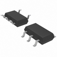
LTC6905CS5#TRPBF Linear Technology, LTC6905CS5#TRPBF Datasheet - Page 7

LTC6905CS5#TRPBF
Manufacturer Part Number
LTC6905CS5#TRPBF
Description
IC OSCILLATOR RES SET TSOT23-5
Manufacturer
Linear Technology
Type
Oscillator, Siliconr
Datasheet
1.LTC6905CS5TRMPBF.pdf
(12 pages)
Specifications of LTC6905CS5#TRPBF
Frequency
170MHz
Voltage - Supply
2.7 V ~ 5.5 V
Current - Supply
14mA
Operating Temperature
-40°C ~ 85°C
Package / Case
TSOT-23-5, TSOT-5, TSOP-5
Lead Free Status / RoHS Status
Lead free / RoHS Compliant
Count
-
Available stocks
Company
Part Number
Manufacturer
Quantity
Price
THEORY OF OPERATION
As shown in the Block Diagram, the LTC6905’s master
oscillator is controlled by the ratio of the voltage between
the V
(I
mately 1V below V
bias voltage.
A resistor R
“locks together” the voltage (V
variation. This provides the LTC6905’s high precision. The
master oscillation frequency reduces to:
To extend the output frequency range, the master oscillator
signal is divided by 1, 2 or 4 before driving OUT (Pin 5).
The LTC6905 is optimized for use with resistors between
10k and 25k, corresponding to oscillator frequencies
between 17.225MHz and 170MHz. The divide-by value is
determined by the state of the DIV input (Pin 4). Tie DIV to
V
+
RES
or drive it to within 0.4V of V
f
MO
). The voltage on the SET pin is forced to approxi-
+
and SET pins and the current entering the SET pin
=
168 5
SET
.
, connected between the V
MHz
R
SET
+
by the PMOS transistor and its gate
•
10
k
Ω
+
+
1 5
– V
+
.
to select ÷1. This is the
SET
MHz
) and current, I
+
and SET pins,
RES
,
highest frequency range, with the master output frequency
passed directly to OUT. The DIV pin may be fl oated or driven
to midsupply to select ÷2, the intermediate frequency
range. The lowest frequency range, ÷4, is selected by
tying DIV to GND or driving it below 0.5V. Figure 1 shows
the relationship between R
frequency, including the overlapping frequencies.
30
25
20
15
10
5
10
Figure 1. R
÷4 ÷2
OUTPUT FREQUENCY (MHz)
60
SET
÷1
vs Output Frequency
SET
110
, divider setting and output
160
6905 F01
LTC6905
6905fd
7


