1-487951-8 TE Connectivity, 1-487951-8 Datasheet

Flex Cable Connector,PCB Mount,18 Contacts,Number Of Contact Rows:1,LOCKING MECH

1-487951-8

Manufacturer Part Number
1-487951-8
Description
Flex Cable Connector,PCB Mount,18 Contacts,Number Of Contact Rows:1,LOCKING MECH
Manufacturer
TE Connectivity
Datasheets

Specifications of 1-487951-8

Rohs Compliant
No
Product Line
2.8 mm
Product Type
Connector
Rohs/elv Compliance
Not ELV/RoHS compliant
Lead Free Solder Processes
Reflow solder capable to 245°C, Reflow solder capable to 260°C
1.
1.1.
1.2.
2.
3.
3.1.
3.2.
3.3.
©2011 Tyco Electronics Corporation,
a TE Connectivity Ltd. Company
All Rights Reserved
TE logo is a trademark.
SCOPE
Content
This specification covers performance, tests and quality requirements for the TE 1 mm FPC connector.
This connector ranges in size from 4 to 30 positions. A single contact is produced with tails to provide
right angle surface mount connections to a printed circuit board. An actuator provides ZIF action and the
socket accepts FEC, FFC, or FPC. The 2 right angle versions of the socket mate with the exposed
traces of the cable facing up or down. Housing can be equipped with solder hold down tabs for both
right angle versions.
Qualification
When tests are performed on the subject product line, procedures specified in 109 Series Test
Specifications shall be used. All inspections shall be performed using the applicable inspection plan and
product drawing.
APPLICABLE DOCUMENTS
The following TE Connectivity (TE) documents form a part of this specification to the extent specified
herein. Unless otherwise specified, the latest edition of the document applies. In the event of conflict
between the requirements of this specification and the product drawing, the product drawing shall take
precedence. In the event of conflict between the requirements of this specification and the referenced
documents, this specification shall take precedence.
!
!
!
!
REQUIREMENTS
Design and Construction
Product shall be of the design, construction and physical dimensions specified on the applicable product
drawing.
Materials
!
!
!
!
Ratings
!
!
!
109-1: General Requirements for Test Specifications
109 Series: Test Specifications as indicated in Figure 1
114-1072: Application Specification
501-278: Qualification Test Report
Actuator: Glass reinforced nylon (PPA), UL94V-0 or glass reinforced PPS UL94V-0
Board mount: Phosphor bronze, tin plating
Contact: Phosphor bronze, tin-lead over nickel plating
Housing: Glass reinforced polyester (LCP), UL94V-0
Voltage: 200 volts AC (rms)
Current: Signal application only, 1 ampere maximum for single circuit
Temperature: -40 to 85° C
| Indicates change
*Trademark
Product
Specification
Connector, FPC, 1 mm
For latest revision, visit our website at www.te.com/documents.
For Regional Customer Service, visit our website at www.te.com
Other products, logos, and company names might be trademarks of their respective owners.
108-1393
11Mar11 Rev C
1 of 6
LOC B

Related parts for 1-487951-8

1-487951-8 Summary of contents

Page 1

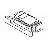
... Content This specification covers performance, tests and quality requirements for the FPC connector. This connector ranges in size from positions. A single contact is produced with tails to provide right angle surface mount connections to a printed circuit board. An actuator provides ZIF action and the socket accepts FEC, FFC, or FPC ...

Page 2

... Performance and Test Description Product is designed to meet the electrical, mechanical and environmental performance requirements specified in Figure 1. Unless otherwise specified, all tests shall be performed at ambient environmental conditions per Test Specification 109-1. 3.5. Test Requirements and Procedures Summary Test Description Examination of product. ...

Page 3

... Figure 2 108-1393 Procedure TE Spec 109-30. Apply axial load off 100 grams to contacts in vertical direction and hold for 30 seconds minimum. TE Spec 109-22. Subject mated samples to 5 cycles between -40 and 85° Spec 109-23-3, Condition B. Subject mated samples to 10 cycles between 25 and 65° 95% RH. Final measurements shall be taken during recovery period ...

Page 4

... Samples shall be prepared in accordance with applicable Instruction Sheets and shall be selected at random from current production. All test groups shall consist of a minimum of 5 connectors. Test groups 1 and 2 shall be soldered to printed circuit boards. A minimum of 30 contacts from these test groups shall be randomly selected and tested. If available, test group 1 shall contain both minimum and maximum size connectors ...

Page 5

... Rev C Figure 3 Termination Resistance Measurement Points 108-1393 ...

Page 6

... Vibration & Mechanical Shock Mounting Fixture Rev C Figure 4 108-1393 ...

Related keywords