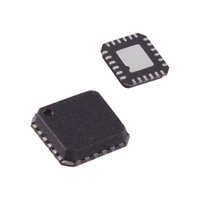
ADF4360-7BCP Analog Devices Inc, ADF4360-7BCP Datasheet - Page 18

ADF4360-7BCP
Manufacturer Part Number
ADF4360-7BCP
Description
IC SYNTHESIZER/VCO 24-LFCSP
Manufacturer
Analog Devices Inc
Type
Fanout Distribution, Integer N Synthesizer (RF)r
Datasheet
1.ADF4360-7BCPZRL.pdf
(28 pages)
Specifications of ADF4360-7BCP
Rohs Status
RoHS non-compliant
Pll
Yes
Input
CMOS
Output
Clock
Number Of Circuits
1
Ratio - Input:output
1:2
Differential - Input:output
No/No
Frequency - Max
1.8GHz
Divider/multiplier
Yes/No
Voltage - Supply
3 V ~ 3.6 V
Operating Temperature
-40°C ~ 85°C
Mounting Type
Surface Mount
Package / Case
24-LFCSP
Frequency-max
1.8GHz
Number Of Elements
1
Pll Input Freq (min)
10MHz
Pll Input Freq (max)
250MHz
Operating Supply Voltage (typ)
3.3V
Operating Temp Range
-40C to 85C
Package Type
LFCSP EP
Output Frequency Range
350 to 1800MHz
Operating Supply Voltage (min)
3V
Operating Supply Voltage (max)
3.6V
Operating Temperature Classification
Industrial
Pin Count
24
For Use With
EVAL-ADF4360-7EBZ1 - BOARD EVALUATION FOR ADF4360-7
Lead Free Status / RoHS Status
Not Compliant
Available stocks
Company
Part Number
Manufacturer
Quantity
Price
Part Number:
ADF4360-7BCPZ
Manufacturer:
ADI/亚德诺
Quantity:
20 000
Company:
Part Number:
ADF4360-7BCPZRL7
Manufacturer:
AD
Quantity:
3 100
Part Number:
ADF4360-7BCPZRL7
Manufacturer:
ADI/亚德诺
Quantity:
20 000
ADF4360-7
Hardware Power-Up/Power-Down
If the part is powered down via the hardware (using the CE pin)
and powered up again without any change to the N counter
register during power-down, the part locks at the correct fre-
quency, because the part is already in the correct frequency
band. The lock time depends on the value of capacitance on the
C
capacitance of 440 nF on this pin enables lock times of <600 µs.
The N counter value cannot be changed while the part is in
power-down, since the part may not lock to the correct
frequency on power-up. If it is updated, the correct program-
ming sequence for the part after power-up is the R counter
latch, followed by the control latch, and finally the N counter
latch, with the required interval between the control latch and N
counter latch, as described in the Initial Power-Up section.
N
pin, which is <10 ms for 10 µF capacitance. The smaller
Rev. A | Page 18 of 28
Software Power-Up/Power-Down
If the part is powered down via the software (using the control
latch) and powered up again without any change to the N
counter latch during power-down, the part locks at the correct
frequency, because the part is already in the correct frequency
band. The lock time depends on the value of capacitance on the
C
capacitance of 440 nF on this pin enables lock times of <600 µs.
The N counter value cannot be changed while the part is in
power-down, because the part may not lock to the correct
frequency on power-up. If it is updated, the correct program-
ming sequence for the part after power-up is to the R counter
latch, followed by the control latch, and finally the N counter
latch, with the required interval between the control latch and N
counter latch, as described in the Initial Power-Up section.
N
pin, which is <10 ms for 10 µF capacitance. The smaller


