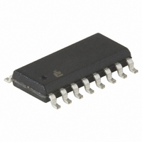
EL4584CS Intersil, EL4584CS Datasheet - Page 10

EL4584CS
Manufacturer Part Number
EL4584CS
Description
IC PLL VIDEO GP 36MHZ 16-SOIC
Manufacturer
Intersil
Type
Phase Lock Loop (PLL)r
Datasheet
1.EL4584CSZ.pdf
(15 pages)
Specifications of EL4584CS
Pll
Yes
Input
Clock
Output
CMOS, TTL
Number Of Circuits
1
Ratio - Input:output
3:1
Differential - Input:output
No/No
Frequency - Max
36MHz
Divider/multiplier
Yes/No
Voltage - Supply
5V
Operating Temperature
-40°C ~ 85°C
Mounting Type
Surface Mount
Package / Case
16-SOIC (3.9mm Width)
Frequency-max
36MHz
Number Of Elements
1
Supply Current
4mA
Operating Supply Voltage (typ)
5V
Operating Temp Range
-40C to 85C
Package Type
SOIC
Operating Temperature Classification
Industrial
Pin Count
16
Frequency
36MHz
Supply Voltage Range
5V
Digital Ic Case Style
SOIC
No. Of Pins
16
Operating Temperature Range
-40°C To +85°C
Peak Reflow Compatible (260 C)
No
Rohs Compliant
No
Lead Free Status / RoHS Status
Contains lead / RoHS non-compliant
Available stocks
Company
Part Number
Manufacturer
Quantity
Price
Company:
Part Number:
EL4584CS
Manufacturer:
Intersil
Quantity:
118
Part Number:
EL4584CS
Manufacturer:
INTERSIL
Quantity:
20 000
Company:
Part Number:
EL4584CSZ
Manufacturer:
Intersil
Quantity:
7
Company:
Part Number:
EL4584CSZ-T7
Manufacturer:
ROHM
Quantity:
2 375
Part Number:
EL4584CSZ-T7
Manufacturer:
EVERLIG
Quantity:
20 000
The above oscillators are arranged as Colpitts oscillators,
and the structure is redrawn here to emphasize the split
capacitance used in a Colpitts oscillator. It should be noted
that this oscillator configuration is just one of literally
hundreds possible, and the configuration shown here does
not necessarily represent the best solution for all
applications. Crystal manufacturers are very informative
sources on the design and use of oscillators in a wide variety
of applications, and the reader is encouraged to become
familiar with them.
C
control from the oscillator, and V1 is the primary control
device. C
maximum modulation capability. The frequency of oscillation
is given by Equations 5 and 6:
Choosing Loop Filter Components
The PLL, VCO, and loop filter can be represented in Figure 15:
F
C
FREQUENCY
1
T
TABLE 4. XTAL VCO COMPONENT VALUES
=
is to adjust the center frequency, C
=
17.734
10.738
12.273
14.318
------------------------- -
12π LC
(MHz)
--------------------------------------------------------------------------
(
C
1
1
2
C
2
should be much larger than C
)
(APPROXIMATE) (Continued)
FIGURE 14. COLPITTS OSCILLATOR
T
+
C
(
C
1
C
1
C
2
C
V
(kΩ)
300
300
300
300
R
)
V
+
1
(
FIGURE 15.
C
2
C
10
V
)
(pF)
C
15
15
15
15
1
2
DC isolates the
V
so that V
0.001
0.001
0.001
0.001
(µF)
C
1
(EQ. 5)
(EQ. 6)
2
has
EL4584
Where:
It can be shown that for the loop filter shown in Equation 7:
C
Where ϖ
factor.
N
1. K
2. The loop bandwidth should be about H
3. N = 910 from Table 2.
4. K
5. Now we can solve for C
6. Notice R
3
K
F(s) = loop filter impedance in V/A
K
N = internal or external divisor
=
=
d
VCO
frequency/20, and the damping ratio should be 1 for
optimum performance. For our example,
ϖ
for each volt applied at the control pin. It is assumed (but
probably is not) linear about the lock point (2.5V). Its
value depends on the VCO configuration and the varactor
transfer function C
bias control voltage, and C
Since F(V
VCO and measure K
such measurement are shown in the following. The slope
of the curve is determined by linear regression
techniques and equals K
K
R
should be large, around 100k, and can be adjusted to
compensate for any static phase error tθ at lock, but if
made too large, will slow loop response. If R
----------------------------------------------------------
H SYNCfrequency
= phase detector gain in A/rad
d
n
VCO
VCO
3
K
----------------------- - C
d
= 300µA/2πrad = 4.77e-5A/rad for the EL4584.
= 15.734kHz/20 = 787Hz≈5000rad/S.
–
= 30kΩ for convenience.
Nω
VCOfrequency
K
= VCO gain in rad/s/V
n
VCO
represents how much the VCO frequency changes
= 6.05 Mrad/S/V.
= loop filter bandwidth, and ζ = loop filter damping
2
n
2
,
C
FIGURE 16. F
has little effect on the loop filter design. R
) is nonlinear, it is probably best to build the
4
=
C
------ - R
10
3
V
,
= F(V
VCO
3
=
OSC
=
3
14.31818M
----------------------------- -
15.73426k
VCO
, C
----------------------- -
K
about 2.5V. The results of one
C
2Nξω
V
d
), where V
4
vs V
K
is varactor capacitance.
, and R
. For our example,
VCO
n
C
, LC VCO
=
3
. We choose
910
C
SYNC
is the reverse
2
is made
May 9, 2008
(EQ. 7)
FN7174.3
(EQ. 8)
2


