SY89538LHH TR Micrel Inc, SY89538LHH TR Datasheet - Page 5
SY89538LHH TR
Manufacturer Part Number
SY89538LHH TR
Description
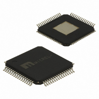
IC SYNTHESIZR LVPECL/LVDS 64TQFP
Manufacturer
Micrel Inc
Series
Precision Edge®r
Type
Clock Synthesizer/Fanout Bufferr
Datasheet
1.SY89538LHY.pdf
(23 pages)
Specifications of SY89538LHH TR
Pll
Yes
Input
CMOS, HSTL, LVDS, LVPECL, LVTTL, SSTL, Crystal
Output
LVDS, LVPECL
Number Of Circuits
1
Ratio - Input:output
2:7
Differential - Input:output
Yes/Yes
Frequency - Max
756MHz
Divider/multiplier
Yes/No
Voltage - Supply
2.375 V ~ 3.6 V
Operating Temperature
0°C ~ 85°C
Mounting Type
Surface Mount
Package / Case
64-TQFP Exposed Pad, 64-eTQFP, 64-HTQFP, 64-VQFP
Frequency-max
756MHz
Lead Free Status / RoHS Status
Lead free / RoHS Compliant
Other names
SY89538LHHTR
SY89538LHHTR
SY89538LHHTR


Pin Description
January 2008
Control and Configuration (continued)
Pin Number
13, 14
46
28
33
35
27
29
34
22
24
26
58
60
5
Pin Name
PDSEL1,
PDSEL0
FBSEL
SYNC
PD_4
PD_2
PD_0
PD_5
PD_3
PD_1
DSEL
PEN0
PEN1
PEN2
PEN3
Pin Function
TTL/CMOS input enable pin. Used to control the PECL POUT0-POUT3 outputs and
as a frequency select pins. PENx, PSELx, and DSEL are used together; see the
“LVPECL Output Post-Divider and Frequency Select Table” for proper decoding.
PENx contains internal 25kΩ pull-up. When disabled, PECL0-PECL3 outputs are a
logic LOW. The threshold voltage V
TTL/CMOS Output Bank Synchronization Control. Internal 25kΩ pull-up. The default
state is HIGH. After any bank has been programmed, all PECL and LVDS outputs are
synchronized when the SYNC control pin is toggled with a HIGH-LOW-HIGH
transition. See “Synchronization” section for details. The threshold voltage V
V
TTL/CMOS Input Select Control. Selects either internal or external feedback (zero-delay
function). Internal 25kΩ pull-up. The threshold voltage V
HIGH, and selects internal feedback.
Logic HIGH: Internal feedback (from the Programmable Divider)
Logic Low: External feedback (from the FBIN inputs)
TTL/CMOS Programmable Divider-Select Control. Internal 25kΩ pull-down. Default is
logic LOW. The threshold voltage V
for proper decoding.
TTL/CMOS Programmable Divider-Select Control. Internal 25kΩ pull-up. Default is logic
HIGH. The threshold voltage V
proper decoding.
TTL/CMOS Pre-Divider Select Input. Internal 25kΩ pull-up. This two-bit input divider
scales the VCO/2 frequency. See “Pre-Divider Frequency Select Table” for proper
decoding. The threshold voltage V
TTL/CMOS Post-Divider Option Control. Internal 25kΩ pull-up. Default is logic HIGH.
The threshold voltage V
Logic HIGH: All LVPECL and LVDS outputs operate with their respective output
frequency control (PSELx, PENx, LSEL, LEN).
Logic LOW: Internal PLL is disabled, reference and XTAL signals by-passes the PLL
through a /1, /4, and /16 Post-Divider.
See “LVPECL and LVDS Output Post-Divider and Frequency Select Table” for proper
decoding.
CC
/2.
5
TH
= V
CC
TH
/2.
= V
TH
TH
CC
= V
TH
= V
/2. See “Programmable-Divider Select Table” for
CC
= V
CC
/2.
/2. See “Programmable-Divider Select Table”
CC
/2.
hbwhelp@micrel.com
TH
= V
CC
/2. Default is logic
or (408) 955-1690
M9999-010808-E
TH
=
Related parts for SY89538LHH TR
Image
Part Number
Description
Manufacturer
Datasheet
Request
R

Part Number:
Description:
3.3V LVPECL/LVDS Clock Synthesizer System - Evaluation Board
Manufacturer:
Micrel Inc
Part Number:
Description:
Manufacturer:
Micrel Inc
Datasheet:
Part Number:
Description:
Manufacturer:
Micrel Inc
Datasheet:
Part Number:
Description:
Manufacturer:
Micrel Inc
Datasheet:
Part Number:
Description:
Manufacturer:
Micrel Inc
Datasheet:
Part Number:
Description:
Manufacturer:
Micrel Inc
Datasheet:
Part Number:
Description:
Manufacturer:
Micrel Inc
Datasheet:
Part Number:
Description:
Manufacturer:
Micrel Inc
Datasheet:
Part Number:
Description:
Manufacturer:
Micrel Inc
Datasheet:
Part Number:
Description:
Manufacturer:
Micrel Inc
Datasheet:
Part Number:
Description:
Manufacturer:
Micrel Inc
Datasheet:
Part Number:
Description:
Manufacturer:
Micrel Inc
Datasheet:
Part Number:
Description:
Manufacturer:
Micrel Inc
Datasheet:
Part Number:
Description:
Manufacturer:
Micrel Inc
Datasheet: