NBSG14BA ON Semiconductor, NBSG14BA Datasheet
NBSG14BA
Specifications of NBSG14BA
Available stocks


Related parts for NBSG14BA

NBSG14BA Summary of contents
Page 1
NBSG14 2.5V/3.3V SiGe Differential 1:4 Clock/Data Driver with RSECL* Outputs *Reduced Swing ECL Description The NBSG14 is a 1−to−4 clock/data distribution chip, optimized for ultra−low skew and jitter. Inputs incorporate internal 50 W termination resistors and accept NECL (Negative ECL), PECL ...
Page 2
A VTCLK CLK VEE VCC C CLK VEE VCC D VTCLK Q0 Q0 Figure 1. BGA−16 Pinout (Top View) Table 1. Pin Description Pin BGA QFN Name I VTCLK − ...
Page 3
V CC VTCLK 50 W CLK CLK VTCLK V EE Figure 3. Logic Diagram Table 2. INTERFACING OPTIONS INTERFACING OPTIONS CML LVDS AC−COUPLED RSECL, PECL, NECL LVTTL, LVCMOS Table 3. ATTRIBUTES Characteristics Internal Input Pulldown Resistor ...
Page 4
Table 4. MAXIMUM RATINGS Symbol Parameter V Positive Power Supply CC V Negative Power Supply EE V Positive Input I Negative Input V Differential Input Voltage |CLK−CLK| INPP I Input Current Through R (50 W Resistor Output ...
Page 5
Table 5. DC CHARACTERISTICS, INPUT WITH RSPECL OUTPUT Symbol Characteristic I Negative Power Supply Current EE V Output HIGH Voltage (Note Output Amplitude Voltage OUTPP V Input HIGH Voltage (Single−Ended) IH (Notes 7 and 9) V Input ...
Page 6
Table 6. DC CHARACTERISTICS, INPUT WITH RSPECL OUTPUT Symbol Characteristic I Negative Power Supply Current EE V Output HIGH Voltage (Note 11 Output Amplitude Voltage OUTPP V Input HIGH Voltage (Single−Ended) IH (Notes 13 and 15) V Input ...
Page 7
Table 7. DC CHARACTERISTICS, NECL OR RSNECL INPUT WITH NECL OUTPUT −3.465 V to −2.375 V (Note 16 Symbol Characteristic I Negative Power Supply Current EE V Output HIGH Voltage (Note 17) ...
Page 8
Table 8. AC CHARACTERISTICS for FCBGA− −3.465 V to −2.375 Symbol Characteristic f Maximum Frequency max (See Figure 4) (Note 22 Propagation Delay to PLH t Output ...
Page 9
Table 9. AC CHARACTERISTICS for QFN− −3.465 V to −2.375 Symbol Characteristic f Maximum Frequency max (See Figure 4) (Note 29 Propagation Delay to PLH t Output ...
Page 10
500 400 300 Ç Ç Ç Ç Ç Ç Ç Ç Ç Ç Ç Ç Ç Ç Ç Ç Ç Ç Ç Ç Ç Ç Ç Ç Ç Ç Ç Ç Ç Ç Ç Ç Ç Ç Ç Ç Ç ...
Page 11
... V (BGA − 2.0 V (QFN Package FCBGA−16 (Pb−Free) FCBGA−16 QFN−16 QFN−16 (Pb−Free) QFN−16 QFN−16 (Pb−Free) QFN−16 (Pb−Free) NBSG14BA Evaluation Board http://onsemi.com (CLK) − V (CLK) INPP (Q) − V (Q) OUTPP OH OL PHL D Receiver Device D † ...
Page 12
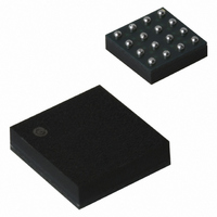
PLASTIC 4X4 (mm) BGA FLIP CHIP PACKAGE LASER MARK FOR PIN 1 IDENTIFICATION IN −X− THIS AREA D −Y− VIEW M− DETAIL K _ ROTATED 90 ...
Page 13
... 0.05 C NOTE 3 *For additional information on our Pb−Free strategy and soldering details, please download the ON Semiconductor Soldering and Mounting Techniques Reference Manual, SOLDERRM/D. N. American Technical Support: 800−282−9855 Toll Free USA/Canada Europe, Middle East and Africa Technical Support: Phone: 421 33 790 2910 Japan Customer Focus Center Phone: 81− ...