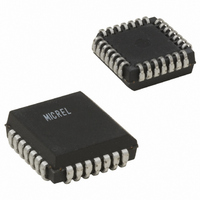
SY100S811JC Micrel Inc, SY100S811JC Datasheet - Page 4

SY100S811JC
Manufacturer Part Number
SY100S811JC
Description
IC DRIVER DIFF 1:9 SGL 28-PLCC
Manufacturer
Micrel Inc
Series
Precision Edge®r
Type
Fanout Buffer (Distribution)r
Datasheet
1.SY100S811ZH.pdf
(6 pages)
Specifications of SY100S811JC
Number Of Circuits
1
Ratio - Input:output
2:9
Differential - Input:output
Yes/Yes
Input
PECL, TTL
Output
PECL
Voltage - Supply
4.75 V ~ 5.25 V
Operating Temperature
0°C ~ 85°C
Mounting Type
Surface Mount
Package / Case
28-LCC (J-Lead)
Lead Free Status / RoHS Status
Contains lead / RoHS non-compliant
Frequency-max
-
Available stocks
Company
Part Number
Manufacturer
Quantity
Price
Part Number:
SY100S811JC
Manufacturer:
SYNERGY
Quantity:
20 000
Part Number:
SY100S811JC-TP
Manufacturer:
SYNERGY
Quantity:
20 000
Micrel, Inc.
V
Notes:
1.
2.
3.
4.
V
Notes:
1. Part-to-part skew is defined as Max. — Min. value at the given temperature.
2. The differential propagation delay is defined as the delay from the crossing points of the differential input signals to the crossing point of the
3. The single-ended propagation delay is defined as the delay from the 50% point of the input signal to the 50% point of the output signal.
4. The within-device skew is defined as the worst case difference between any two similar delay paths within a single device.
5. V
6. V
M9999-021407
hbwhelp@micrel.com or (408) 955-1690
Symbol
Symbol
V
V
I
I
V
t
t
t
V
V
t
t
CC
CC
IH
IL
V
V
V
PLH
PHL
skew
r
f
TTL DC ELECTRICAL CHARACTERISTICS
AC ELECTRICAL CHARACTERISTICS
I
differential output signals.
the S811, as a differential input as low as 50mV will still produce full PECL levels at the output.
be such that the peak-to-peak voltage is less than 1.0V and greater than or equal to V
IH
IL
IK
PP
CMR
IN
IN
IN
IN
PP
CMR
= V
= V
= -18
= 2.7V
= 5.0V
= 0.5V
(min.) is defined as the minimum input differential voltage which will cause no increase in the propagation delay. The V
is defined as the range within which the V
CCO
CCO
mA
Input HIGH Voltage
Input LOW Voltage
Input HIGH Current
Input LOW Current
Input Clamp Voltage
Propagation Delay to Output
E
E
T
Within-Device skew
Minimum PECL Input Swing
PECL Common Mode Range
Output Rise/Fall Times
20% to 80%
IN
= +5.0V
= +5.0V
IN
IN
(differential)
(single-ended)
Parameter
Parameter
5%
5%
(2)
(3)
(3)
(1),(2)
(4)
(4)
(5)
(1)
(6)
IH
level may vary, with the device still meeting the propagation delay specification. The V
Min.
Min.
–1.6
430
330
350
250
275
2.0
—
—
—
—
—
—
T
T
(1–6)
A
Typ.
A
Typ.
375
25
—
—
—
—
—
—
—
—
—
—
—
= 0 C
= 0 C
Max.
Max.
–0.6
–1.2
–0.4
100
630
730
950
600
0.8
20
50
4
—
—
Min.
Min.
–1.6
430
330
350
250
275
2.0
—
—
—
—
—
—
PP
T
T
(min.).
A
A
= +25 C
= +25 C
Typ.
Typ.
375
25
—
—
—
—
—
—
—
—
—
—
—
Max.
Max.
–0.6
–1.2
–0.4
100
630
730
950
600
0.8
20
50
—
—
Min.
Min.
–1.6
430
330
350
250
275
2.0
—
—
—
—
—
—
T
T
A
A
= +85 C
= +85 C
Typ.
Typ.
375
PP
25
—
—
—
—
—
—
—
—
—
—
—
(min.) is AC limited for
Precision Edge
Max.
Max.
–0.6
–1.2
–0.4
100
630
730
950
600
0.8
20
50
—
—
SY100S811
IL
level must
Unit
Unit
mA
mV
ps
ps
ps
V
V
V
V
A
®


