SY89825UHG TR Micrel Inc, SY89825UHG TR Datasheet - Page 4
SY89825UHG TR
Manufacturer Part Number
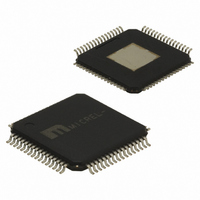
SY89825UHG TR
Description
IC BUS CLK DRVR LVPECL 64-TQFP
Manufacturer
Micrel Inc
Series
Precision Edge®r
Type
Fanout Buffer (Distribution), Multiplexer , Translatorr
Datasheet
1.SY89825UHY.pdf
(9 pages)
Specifications of SY89825UHG TR
Number Of Circuits
1
Ratio - Input:output
2:22
Differential - Input:output
Yes/Yes
Input
LVDS, LVPECL
Output
LVPECL
Frequency - Max
2GHz
Voltage - Supply
2.37 V ~ 3.6 V
Operating Temperature
-40°C ~ 85°C
Mounting Type
Surface Mount
Package / Case
64-TQFP Exposed Pad, 64-eTQFP, 64-HTQFP, 64-VQFP
Frequency-max
2GHz
Lead Free Status / RoHS Status
Lead free / RoHS Compliant
Other names
SY89825UHGTR
SY89825UHGTR
SY89825UHGTR


Micrel, Inc.
Power Supply
Notes:
1. V
2. No load. Outputs floating.
LVDS Input (V
Note:
1. For I
LVPECL Input/Output (V
Notes:
1. The V
2. V
3. Outputs loaded with 50 to V
LVCMOS/LVTTL Control Inputs (OE, CLK_SEL) (V
M9999-011907
hbwhelp@micrel.com or (408) 955-1690
Symbol
V
V
I
R
Symbol
V
V
V
V
V
V
I
I
Symbol
V
V
I
I
Symbol
V
V
I
IL
IH
IL
IH
IL
CC
DC ELECTRICAL CHARACTERISTICS
IN
ID
IH
IL
PP
CMR
OH
OL
referenced to V
CMR range varies 1:1 with V
IH
IL
CCI,
CCO
IN
CCI
CMR
IL
and V
is defined as the range within which the V
, both LVDS inputs are grounded.
PP
(min.) is defined as the minimum input differential voltage which will cause no increase in the propagation delay.
Input Voltage Range
Differential Input Swing
Input Low Current
LVDS Differential Input Resistance
(LVDS_CLK to /LVDS_CLK)
Input HIGH Voltage
(Single ended)
Input LOW Voltage
Minimum Input Swing
LVPECL_CLK
Common Mode Range
LVPECL_CLK
Output HIGH Voltage
Output LOW Voltage
Input HIGH Current
Input LOW Current
Input HIGH Voltage
Input LOW Voltage
Input HIGH Current
Input LOW Current
Power Supply
Total Supply Current
CCO
CCI
must be connected together on the PCB such that they remain at the same potential. V
CC
. The V
= 2.37V to 3.6V, GND = 0V)
Parameter
Parameter
Parameter
Parameter
IL
(1)
level must be such that the peak-to-peak voltage is less than 1.0V and greater than or equal to V
CCI
CC
. The V
-2V.
CC
(1)
(2)
= 2.37V to 3.6V, GND = 0V)
(3)
(3)
(1)
(2)
CMR
(min) will be fixed at 3.3V – |V
IH
level may vary, with the device still meeting the propagation delay specification. The numbers in the table are
V
V
V
V
CCO
CCO
CC
CC
Min.
–1.5
600
– 1.165
0.5
–1.25
– 1.945
—
Min.
– 1.085 V
– 1.830 V
Min.
Min.
2.37
100
+20
2.0
80
—
—
—
0
T
A
= –40 C
T
T
T
A
A
A
= –40 C
= –40 C
= –40 C
Typ.
Typ.
Typ.
V
100
100
V
CCO
CCO
—
—
—
—
CC
—
—
—
—
CC
CC
Max.
–0.4
150
– 1.625 V
= 2.37V to 3.6V, GND = 0V)
—
—
– 0.88
– 0.880 V
– 1.555 V
CMR
Max.
Max.
Max.
–250
–600
4
150
120
3.6
2.4
0.8
(min)|.
—
—
—
V
CCO
CCO
CC
CC
–1.25
Min.
–1.5
Min.
Min.
600
Min.
2.37
100
0.5
+20
– 1.165
– 1.945
2.0
—
80
—
—
—
– 1.025 V
– 1.810 V
0
T
A
T
T
T
A
A
A
= +25 C
= +25 C
= +25 C
= +25 C
Typ.
Typ.
Typ.
100
100
—
—
—
—
—
—
—
—
V
V
CCI
CCO
CCO
CC
CC
Max.
and V
–0.4
150
– 1.625
—
—
– 0.88
– 0.880 V
– 1.620 V
Max.
Max.
–250
–600
Max.
150
120
3.8
2.4
0.8
—
—
—
CCO
are not internally connected on the die.
V
V
CCO
CCO
CC
CC
–1.25
Min.
Min.
Min.
2.37
+20
100
2.0
80
—
—
—
Min.
–1.5
0
600
0.5
PP
– 1.165
– 1.945
—
– 1.025 V
– 1.810 V
(min.). The lower end of the
T
T
T
T
A
A
A
A
= +85 C
= +85 C
= +85 C
= +85 C
Typ.
Typ.
Typ.
100
100
—
—
—
—
—
—
—
—
V
V
CCO
CCO
CC
CC
Precision Edge
Max.
–0.4
150
– 1.625
—
—
– 0.88
– 0.880
– 1.620
Max.
Max.
–250
–600
Max.
120
150
2.4
0.8
3.6
—
—
—
SY89825U
Unit
Unit
Unit
Unit
mA
mV
mA
mV
V
V
V
V
V
V
V
V
V
A
A
A
A
®
Related parts for SY89825UHG TR
Image
Part Number
Description
Manufacturer
Datasheet
Request
R

Part Number:
Description:
Manufacturer:
Micrel Inc
Datasheet:
Part Number:
Description:
Manufacturer:
Micrel Inc
Datasheet:
Part Number:
Description:
Manufacturer:
Micrel Inc
Datasheet:
Part Number:
Description:
Manufacturer:
Micrel Inc
Datasheet:
Part Number:
Description:
Manufacturer:
Micrel Inc
Datasheet:
Part Number:
Description:
Manufacturer:
Micrel Inc
Datasheet:
Part Number:
Description:
Manufacturer:
Micrel Inc
Datasheet:
Part Number:
Description:
Manufacturer:
Micrel Inc
Datasheet:
Part Number:
Description:
Manufacturer:
Micrel Inc
Datasheet:
Part Number:
Description:
Manufacturer:
Micrel Inc
Datasheet:
Part Number:
Description:
Manufacturer:
Micrel Inc
Datasheet:
Part Number:
Description:
Manufacturer:
Micrel Inc
Datasheet:
Part Number:
Description:
Manufacturer:
Micrel Inc
Datasheet:
Part Number:
Description:
Manufacturer:
Micrel Inc
Datasheet: