SY89832UMG Micrel Inc, SY89832UMG Datasheet - Page 5
SY89832UMG
Manufacturer Part Number
SY89832UMG
Description
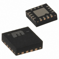
IC BUFFER/XLATOR 1:4 LVDS 16MLF
Manufacturer
Micrel Inc
Series
Precision Edge®r
Type
Fanout Buffer (Distribution), Translatorr
Datasheet
1.SY89832UMG.pdf
(10 pages)
Specifications of SY89832UMG
Number Of Circuits
1
Ratio - Input:output
1:4
Differential - Input:output
Yes/Yes
Input
CML, LVDS, LVPECL
Output
LVDS
Frequency - Max
2.5GHz
Voltage - Supply
2.375 V ~ 2.625 V
Operating Temperature
-40°C ~ 85°C
Mounting Type
Surface Mount
Package / Case
16-MLF®, QFN
Frequency-max
2.5GHz
Clock Ic Type
Clock Divider / Fan-out Buffer
Frequency
2.5GHz
No. Of Outputs
4
Ic Output Type
LVDS
Supply Current
75mA
Supply Voltage Range
2.375V To 2.325V
Digital Ic Case Style
MLF
Number Of Outputs
8
Operating Supply Voltage (max)
2.625V
Operating Temp Range
-40C to 85C
Propagation Delay Time
0.57ns
Operating Supply Voltage (min)
2.375V
Mounting
Surface Mount
Pin Count
16
Operating Supply Voltage (typ)
2.5V
Package Type
MLF
Input Frequency
2.5GHz
Operating Temperature Classification
Industrial
Lead Free Status / RoHS Status
Lead free / RoHS Compliant
Other names
576-1432
Available stocks
Company
Part Number
Manufacturer
Quantity
Price
Company:

Part Number:
SY89832UMG
Manufacturer:
MICREL
Quantity:
41
Part Number:
SY89832UMG
Manufacturer:
MICREL/麦瑞
Quantity:
20 000
Part Number:
SY89832UMGTR
Manufacturer:
MICREL
Quantity:
20 000


Micrel, Inc.
V
Symbol
f
t
t
t
t
t
t
Notes:
7.
8.
9.
10. Set-up and hold times apply to synchronous applications that intend to enable/disable before the next clock cycle. For asynchronous applications,
11. Random jitter is measured with a K28.7 pattern, measured at -f
12. Deterministic jitter is measured at 2.5Gbps with both K28.5 and 2
13. Cycle-to-cycle jitter definition: The variation period between adjacent cycles over a random sample of adjacent cycle pairs.
14. Total jitter definition: with an ideal clock input frequency of - f
August 2007
MAX
pd
SKEW
S
H
JITTER
r
, t
CC
AC ELECTRICAL CHARACTERISTICS
TIMING DIAGRAM
f
High-frequency AC parameters are guaranteed by design and characterization.
Within device skew is measured between two different outputs under identical input transitions.
Part-to-part skew is defined for two parts with identical power supply voltages at the same temperature and no skew at the edges at the respective
inputs.
set-up and hold times do not apply.
t
than the specified peak-to-peak jitter value.
= +2.5V ±5% or +3.3V ±10%; R
JITTER_CC
= T
Parameter
Maximum Frequency
Propagation Delay
Within-Device Skew
Part-to-Part Skew
Set-Up Time
Hold Time
Data
Clock
Output Rise/Fall Times
(20% to 80%)
n
Random Jitter (RJ)
Deterministic Jitter (DJ)
Cycle-to-Cycle Jitter
Total Jitter (TJ)
–T
n+1
EN
/IN
/Q
IN
Q
, where T is the time between rising edges of the output signal.
V
IN
L
t
pd
= 100ý across the outputs; T
EN to IN, /IN
EN to IN, /IN
V
t
S
CC
/2
IN-to-Q
IN-to-Q
Condition
V
V
V
Note 8
Note 9
Note 10
Note 10
Note 11
Note 12
Note 13
Note 14
At full output swing.
OUT
IN
IN
(7)
< 400mV
ž 400mV
MAX
ž 200mV
MAX
t
23
H
(device), no more than one output edge in 10
–1 PRBS pattern.
.
A
5
V
= –40°C to +85°C unless otherwise stated.
CC
/2
hbwhelp@micrel.com or (408) 955-1690
Min
370
300
300
500
12
2.0
70
output edges will deviate by more
V
OUT
Typ
470
410
150
2.5
5
Precision Edge
Max
570
500
200
200
20
10
10
M9999-082407
1
1
SY89832U
ps
ps
Units
ps
ps
GHz
ps
ps
ps
ps
ps
ps
ps
RMS
RMS
PP
PP
®
Related parts for SY89832UMG
Image
Part Number
Description
Manufacturer
Datasheet
Request
R

Part Number:
Description:
3.3V 800MHz Ultrasmall Dual LVTTL-to-LVPECL Translator (I Temp, Green)
Manufacturer:
Micrel Inc
Datasheet:

Part Number:
Description:
IC XPOINT SW 4X4 PREC 44-MLF
Manufacturer:
Micrel Inc
Datasheet:
Part Number:
Description:
IC XPOINT SWITCH 3.2GBPS 44-MLF
Manufacturer:
Micrel Inc
Datasheet:
Part Number:
Description:
IC XPOINT SWITCH 3.2GBPS 44-MLF
Manufacturer:
Micrel Inc
Datasheet:
Part Number:
Description:
IC XPOINT SWITCH 4X4 LVDS 44-MLF
Manufacturer:
Micrel Inc
Datasheet:
Part Number:
Description:
IC XPOINT SWITCH 4X4 LVDS 44-MLF
Manufacturer:
Micrel Inc
Datasheet:

Part Number:
Description:
IC MUX 2:1 LVPECL DIFF 16MLF
Manufacturer:
Micrel Inc
Datasheet:
Part Number:
Description:
IC MUX 2:1 LVPECL RPE/FSI 16MLF
Manufacturer:
Micrel Inc
Datasheet:
Part Number:
Description:
IC MUX 2:1 LVDS RPE 16-MLF
Manufacturer:
Micrel Inc
Datasheet:
Part Number:
Description:
IC MUX 8:1 PREC LP 44-MLF
Manufacturer:
Micrel Inc
Datasheet:

Part Number:
Description:
IC MUX 2:1 LVDC DUAL 3.3V 32MLF
Manufacturer:
Micrel Inc
Datasheet:
Part Number:
Description:
IC MUX 4:1 LVDS DIFF 2.5V 32MLF
Manufacturer:
Micrel Inc
Datasheet:
Part Number:
Description:
IC MUX 4:1 LVDS DIFF 3.3V 32MLF
Manufacturer:
Micrel Inc
Datasheet:
Part Number:
Description:
IC MUX 4:1 LVDS DIFF 2.5V 32MLF
Manufacturer:
Micrel Inc
Datasheet:
Part Number:
Description:
IC MUX 4:1 LVDS DIFF 3.3V 32MLF
Manufacturer:
Micrel Inc
Datasheet: