SY87702LHI Micrel Inc, SY87702LHI Datasheet - Page 5
SY87702LHI
Manufacturer Part Number
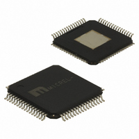
SY87702LHI
Description
IC CLOCK/DATA RECOVERY 64-TQFP
Manufacturer
Micrel Inc
Type
Clock and Data Recovery (CDR)r
Datasheet
1.SY87702LHI.pdf
(14 pages)
Specifications of SY87702LHI
Input
Differential
Output
Differential
Frequency - Max
325MHz
Voltage - Supply
3.15 V ~ 3.45 V
Operating Temperature
-40°C ~ 85°C
Mounting Type
Surface Mount
Package / Case
64-TQFP Exposed Pad, 64-eTQFP, 64-HTQFP, 64-VQFP
Frequency-max
325MHz
Lead Free Status / RoHS Status
Contains lead / RoHS non-compliant


Micrel, Inc.
Clock Recovery
generates a clock that is at the same frequency as the
incoming data bit rate at the Serial Data input. The clock is
phase aligned by a PLL so that it samples the data in the
center of the data eye pattern.
the data and those of the generated clock are compared by
a phase/frequency detector. Output pulses from the detector
indicate the required direction of phase correction. These
pulses are smoothed by an integral loop filter. The output of
the loop filter controls the frequency of the Voltage Controlled
Oscillator (VCO), which generates the recovered clock.
by an alternate reference input (REFCLK) that the PLL locks
onto when data is lost. If the Frequency of the incoming
signal varies by greater than approximately 1000ppm with
respect to the synthesizer frequency, the PLL will be declared
out of lock, and the PLL will lock to the multiplied frequency
of the reference clock.
PLL to track the jitter, yet tolerate the minimum transition
density expected in a received SONET data signal. This
transfer function yields a 30µs data stream of continuous
1's or 0's for random incoming NRZ data.
provides jitter tolerance which is better than the specified
tolerance in GR-253-CORE.
M9999-072706
hbwhelp@micrel.com or (408) 955-1690
FUNCTIONAL DESCRIPTION
Clock Recovery, as shown in the block diagram,
The phase relationship between the edge transitions of
Frequency stability, without incoming data, is guaranteed
The loop filter transfer function is optimized to enable the
The total loop dynamics of the clock recovery PLL
5
INPUTS
RDIN
stream. An internal receive PLL recovers the embedded
clock (RCLK) and data (RDOUT) information. The incoming
data rate can be within one of ten frequency ranges, or can
be one of five specific frequencies, depending on the state
of the FREQSEL and VCOSEL pins. The RDIN– pin has an
internal 75KΩ resistor tied to V
REFCLK
frequency synthesizer and the “training” frequency for the
receiver PLL to keep it centered in the absence of data
coming in on the RDIN input. The input frequency to
REFCLK is limited to 325MHz or less, depending on the
setting on the DIVSEL signals. The REFCLK– pin has an
internal 75KΩ resistor tied to V
CD [Carrier Detect] – PECL Input
PLL and can be driven by the carrier detect output of optical
modules or from external transition detection circuitry. When
this input is HIGH, the input data stream (RDIN) is recovered
normally by the Receive PLL. When this input is LOW, the
data on the RDIN input will be internally forced to a constant
LOW, the data output RDOUT will remain LOW, the Link
Fault Indicator output LFIN forced LOW, and the clock
recovery PLL forced to lock onto the clock frequency
generated from REFCLK.
VCOSEL1, VCOSEL2 [VCO Select] – TTL Inputs
one of three wide-band PLLs, or a SONET/SDH specific
narrow-band PLL. Only the selected PLL is enabled. All
other PLL’s are disabled. Please refer to Table 1.
PIN NAMES
This differential input accepts the receive serial data
This input is used as the reference for the internal
This input controls the recovery function of the Receive
These inputs select the VCO frequency range via either
VCOSEL1
±
[Serial Data Input] – Differential PECL
0
0
1
1
±
[Reference Clock] – Differential PECL
VCOSEL2
Table. 1
0
1
0
1
CC
CC
.
.
0.650 to 1.30GHz
1.25 to 1.8GHz
1.8 to 2.5GHz
SONET/SDH
Choice
SY87702L
Related parts for SY87702LHI
Image
Part Number
Description
Manufacturer
Datasheet
Request
R

Part Number:
Description:
Manufacturer:
Micrel Inc
Datasheet:
Part Number:
Description:
Manufacturer:
Micrel Inc
Datasheet:
Part Number:
Description:
Manufacturer:
Micrel Inc
Datasheet:
Part Number:
Description:
Manufacturer:
Micrel Inc
Datasheet:
Part Number:
Description:
Manufacturer:
Micrel Inc
Datasheet:
Part Number:
Description:
Manufacturer:
Micrel Inc
Datasheet:
Part Number:
Description:
Manufacturer:
Micrel Inc
Datasheet:
Part Number:
Description:
Manufacturer:
Micrel Inc
Datasheet:
Part Number:
Description:
Manufacturer:
Micrel Inc
Datasheet:
Part Number:
Description:
Manufacturer:
Micrel Inc
Datasheet:
Part Number:
Description:
Manufacturer:
Micrel Inc
Datasheet:
Part Number:
Description:
Manufacturer:
Micrel Inc
Datasheet:
Part Number:
Description:
Manufacturer:
Micrel Inc
Datasheet:
Part Number:
Description:
Manufacturer:
Micrel Inc
Datasheet: