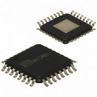
SY87701LHI Micrel Inc, SY87701LHI Datasheet - Page 5

SY87701LHI
Manufacturer Part Number
SY87701LHI
Description
IC CLOCK/DATA RECOVERY 32-TQFP
Manufacturer
Micrel Inc
Type
Clock and Data Recovery (CDR)r
Datasheet
1.SY87701LHG.pdf
(14 pages)
Specifications of SY87701LHI
Input
PECL, TTL
Output
PECL, TTL
Frequency - Max
1.25GHz
Voltage - Supply
3.15 V ~ 3.45 V
Operating Temperature
-40°C ~ 85°C
Mounting Type
Surface Mount
Package / Case
32-TQFP Exposed Pad, 32-eTQFP, 32-HTQFP, 32-VQFP
Frequency-max
1.25GHz
Date Format
Binary
Clock Format
Binary
Digital Ic Case Style
TQFP
No. Of Pins
32
Peak Reflow Compatible (260 C)
No
Supply Voltage
3.3V
Ic Interface Type
Serial
Supply Voltage Max
3.3V
Leaded Process Compatible
No
Lead Free Status / RoHS Status
Contains lead / RoHS non-compliant
Available stocks
Company
Part Number
Manufacturer
Quantity
Price
Micrel, Inc.
Performance
proposed for SONET/SDH equipment defined by the Bellcore
Specifications: GR-253-CORE, Issue 2, December 1995 and
ITU-T Recommendations: G.958 document, when used with
differential inputs and outputs.
Input Jitter Tolerance
amplitude of sinusoidal jitter applied on the input signal that
causes an equivalent 1dB optical/electrical power penalty.
SONET input jitter tolerance requirement condition is the
input jitter amplitude which causes an equivalent of 1dB
power penalty.
M9999-111506
hbwhelp@micrel.com or (408) 955-1690
CHARACTERISTICS
The SY87701L PLL complies with the jitter specifications
Input jitter tolerance is defined as the peak-to-peak
OC/STS-N
0.40
Level
15
1.5
A
12
3
Figure 1. Input Jitter Tolerance
(Hz)
f0
10
10
f0
f1
(Hz)
30
30
f1
-20dB/decade
f2
Frequency
(Hz)
300
300
f2
f4
(kHz)
6.5
25
f3
-20dB/decade
ft
(kHz)
250
65
ft
5
Jitter Transfer
the output OC-N/STS-N signal to the jitter applied on the
input OC-N/STS-N signal versus frequency. Jitter transfer
requirements are shown in Figure 2.
Jitter Generation
not exceed .01 U.I. rms when a serial data input with no
jitter is presented to the serial data inputs.
Jitter transfer function is defined as the ratio of jitter on
The jitter of the serial clock and serial data outputs shall
-20
0.1
OC/STS-N
Level
12
3
Acceptable
Range
Figure 2. Jitter Transfer
Jitter Transfer (dB)
fc
(kHz)
130
225
fc
-20dB/decade
Frequency
(dB)
0.1
0.1
P
SY87701L


