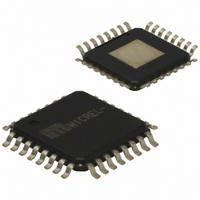
SY87739LHI Micrel Inc, SY87739LHI Datasheet - Page 7

SY87739LHI
Manufacturer Part Number
SY87739LHI
Description
IC SYNTHESIZER FRACT 3.3V 32TQFP
Manufacturer
Micrel Inc
Type
Fractional Synthesizerr
Datasheet
1.SY87739LHY.pdf
(13 pages)
Specifications of SY87739LHI
Input
PECL
Output
PECL
Frequency - Max
729MHz
Voltage - Supply
3.15 V ~ 3.45 V
Operating Temperature
-40°C ~ 85°C
Mounting Type
Surface Mount
Package / Case
32-TQFP Exposed Pad, 32-eTQFP, 32-HTQFP, 32-VQFP
Frequency-max
729MHz
For Use With
576-1406 - BOARD EVAL N SY87739 EXPERIMENT
Lead Free Status / RoHS Status
Contains lead / RoHS non-compliant
Available stocks
Company
Part Number
Manufacturer
Quantity
Price
Company:
Part Number:
SY87739LHI
Manufacturer:
SYNERGY
Quantity:
11
Micrel, Inc.
Fractional-N Control
appropriate divide ratio, either P or P–1, in the correct
pattern.
the P/P–1 divider amounts to generating a repeating binary
bit stream. In that example, a “1” represents dividing by 4,
and a “0” represents dividing by 3. The full cycle, “101”,
says to divide by 4 twice, and to divide by 3 once.
based on the P divider value. To multiply by 14/3 instead of
11/3, for example, the same “101” pattern would be used,
but we would alternate dividing by 5 and 4, instead of dividing
by 4 and 3. The P value, in effect, represents the integer
part of the multiplication factor.
the number of times to divide by P, and the number of
times to divide by P–1. We label the number of times to
divide by P as Q
P–1 as Q
output frequency as per this formula:
Matching against the formula, P = 4, Q
MicroWire™ interface, where they exist as the 5-bit values
“qp” and “qpm1.” Both values are unsigned binary numbers.
Q
sum is also constrained to be 31 or less. That means that the
denominator in the above formula must be 31 or less.
causes frequency multiplication exactly by P–1. Setting Q
to zero causes frequency multiplication exactly by P. The
SY87739L behavior is undefined if both Q
both set to zero.
pattern is Q
Bresenham’s algorithm in hardware. To see how this works,
we need a more complicated example. Let’s say we need to
multiply by 110/23, or 5 – 5/23. In this example, P = 5,
Q
a bit pattern of:
readability only. This pattern is 23 bits long, with Q
18) “1” and Q
but it doesn’t match P/P–1 divider edges to input edges in
the best way possible.
between divider and reference input edges, is:
M9999-062807
hbwhelp@micrel.com or (408) 955-1690
P
P–1
This circuit controls the P/P–1 divider, selecting the
As explained in the example of Figure 2 above, controlling
In the general case, the pattern “101” need not change
The repeating binary bit pattern really depends only on
In our figure two example, we multiply by 11/3, or 4
The SY87739L accepts Q
As would be expected from the formula, setting Q
In the general case, the length of the repeating binary bit
The SY87739L accomplishes this by implementing
11111 11111 11111 11100 000
The spaces between groups of five digits are added for
In fact, the best pattern, in terms of minimizing distance
and Q
= 5, and Q
f
FNOUT
P-1
P–1
P
+ Q
are both constrained to be 31 or less, and their
=
. The fractional-N synthesizer generates its
P–1
⎡
⎢
⎢
⎣
P
P –
P–1
P
= 18. The naïve approach would generate
(that is, 5) “0”, so it will multiply correctly,
, and the number of times to divide by
. It consists of Q
Q
P
Q
+
P–1
Q
P–1
P
⎤
⎥
⎥
⎦
×
and Q
f
REF
P
“1”, and Q
P–1
P–1
= 1, and Q
P
values from its
and Q
P–1
P
“0.”
P
P–1
(that is,
to zero
P
= 2.
are
P–1
1
/
3
.
7
first column is an accumulator. It starts at zero, but otherwise
takes the result from the fourth column of the previous row.
The second column is the value to add to the accumulator
at each step. In the general case, this is always Q
third column forms the sum. The fourth column takes the
sum modulo (Q
sum. Note that the Table has 23 rows, before the sum is
zero, and the entire algorithm repeats itself.
down, is the optimal pattern to generate.
a fractional-N synthesizer relies on edges temporarily not
matching, but averaging out over some time interval.
Anything that reduces the timing disparity between edges
arriving at the phase-frequency comparator will reduce jitter.
Center Frequency Trim
voltages for the two VCO on the SY87739L. This voltage
pair can be digitally trimmed. Trimming occurs under control
of the acquisition sequencer, which trims for center frequency
of the fractional-N synthesizer only. The wrapper synthesizer
VCO is matched to the fractional-N VCO. Both VCO are fed
11110 11110 1110 11110 1110
Table 2 shows how Bresenham’s algorithm works. The
The last column is “0” whenever the modulo changes the
Accum
Note that the sequence of bits in the last column, reading
The choice of repeating bit pattern reduces jitter because
This circuit block generates two identical reference
10
15
20
12
17
22
14
19
11
16
21
13
18
0
5
2
7
4
9
1
6
3
8
P
Add
5
5
5
5
5
5
5
5
5
5
5
5
5
5
5
5
5
5
5
5
5
5
5
+ Q
Table 2. 5/23 Example
P–1
).
Sum
10
15
20
25
12
17
22
27
14
19
24
11
16
21
26
13
18
23
5
7
9
6
8
Modulo
10
15
20
12
17
22
14
19
11
16
21
13
18
5
2
7
4
9
1
6
3
8
0
SY87739L
P–1
Bit
1
1
1
1
0
1
1
1
1
0
1
1
1
0
1
1
1
1
0
1
1
1
0
. The


