DPM125L Martel Electronics, DPM125L Datasheet - Page 2
DPM125L
Manufacturer Part Number
DPM125L
Description
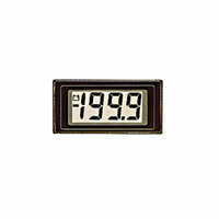
METER DPM LCD3.5DIGIT 200MV BKLT
Manufacturer
Martel Electronics
Series
Legacyr
Type
Voltmeterr
Datasheet
1.DPM125.pdf
(2 pages)
Specifications of DPM125L
Measuring Range
0 ~ 199.9V
Display Style
Black Characters, Grey Background
Display Type
LCD
Display Face Size
1.22" L x 0.55" W (31.0 x 14.0mm)
Display Digits
3.5
Display Digits - Height
0.492" (12.50mm)
Backlight
Without
Mounting Type
Panel Mount
Termination
PC Pins
Voltage - Supply
7.5 ~ 14V
Other names
227-1008


PIN FUNCTIONS
SAFETY
To comply with the Low Voltage Directive (LVD 93/68/EEC), input voltages to the module’s pins must not exceed 60Vdc. If voltages to the
measuring inputs do exceed 60Vdc, then fit scaling resistors externally to the module. The user must ensure that the incorporation of the
DPM into the user’s equipment conforms to the relevant sections of BS EN 61010 (Safety Requirements for Electrical Equipment for
Measuring, Control and Laboratory Use).
Specifications liable to change without prior warning
10. RLO
11. RHI
12. ROH
1. DP1
2. DP2
3. DP3
4. TEST
5. V-
6. V+
7. IN HI
8. INLO
9. COM
VARIOUS OPERATING MODES
ON-BOARD LINKS: In order to quickly and easily change operating modes for
different applications, the meter has several on-board links. They are designed
to be easily cut (opened) or shorted (soldered).
Do not connect more than one meter to the same power supply if the meters cannot
use the same signal ground. Taking any input beyond the power supply rails will
damage the meter.
±200mV
Check Links 2 & 3 are SHORTED.
Measuring current. Supply MUST
be isolated.
Measuring a floating voltage source
of 200mV full scale.
Check Links 2 & 3 are SHORTED.
+
-
+
-
199.9
19.99
1.999
Connect to V+ to display segments as illustrated. It should not be operated for more than a few seconds as the d.c. voltage applied
to the LCD may 'burn' the display. This pin is normally at 5V below V+ and is the ground for the digital section of the meter. It can be
used to power external logic up to a maximum of 1mA.
Negative power supply connection.
Positive power supply connection.
Positive measuring differential input.
Negative measuring differential input.
The ground for the analogue section of the A/D converter, held actively at 2.8V (nom.) below V+. COM must not be allowed to sink
excessive current (>100 A) by connecting it directly to a higher voltage.
Negative input for reference voltage (can be connected to COM via Link 3).
Positive input for reference voltage (connected via Link 1 to ROH).
Positive output from internal reference.
7
8
R=0.2
R
IN LO
IN HI
- -
IF.S.R.
V-
V+
6
5
7
8
Connect to V+ to display required DP .
V+
IN
IN
V-
HI
LO
V-
V+
5
6
V+
V-
Martel Electronics, Corp. P.O. Box 770 Londonderry, NH 03053
Toll Free: (800) 821-0023 Phone: (603) 434-1433 Fax: (603) 434-1653
Analogue inputs must be no closer than 1V to either the positive or negative supply.
±200mV
Split supply operation.
Measuring the ratio of two voltages.
Reading = 1000 V /V
50mV< V <200mV
V <2V .
DPM 125
Check Link 3 is SHORTED.
1
Check Links 1 & 4 are OPEN.
2
0V
+
V
V
-
1V
min.
2
2
1
+
+
-
-
10
11
7
8
8
7
V+
IN HI
IN LO
IN HI
IN LO
REF HI
REF LO
1
Issue 3
2
V-
V+
V-
V+
6
6
5
5
V+
V-
V-
14V max
7V min
August/1997
Normally
SHORTED
Cut to
OPEN
Measuring a supply voltage.
Measuring 4-20mA to read 0-999.
(supply MUST be isolated).
(min. 7.5V, max. 14V).
SUPPLY
VOLTAGE
Check Link 3 is SHORTED.
6R2
I
M.C.
I
OUT
Check Link 3 is SHORTED.
IN
100K
5K
SET
ZERO
10K
510K
510K
7
8
7
9
8
IN LO
IN
IN HI
COM
IN
Applies to DPM 125/2
V+
LO
HI
V-
V-
6
5
V+
6
5
V+
V-
V+
V-
Normally
OPEN
Solder to
SHORT