Tel +1 (717) 767-6511
Fax +1 (717) 764-0839
www.redlion.net
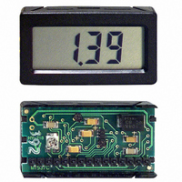
MODEL MDMV - MINIATURE DISPLAY MODULE D.C. VOLTMETER
DESCRIPTION
With advantages of accuracy, size, and ease of installation, it is an ideal
replacement for analog meters. The unit has a 3½-digit LCD display with 0.4"
(10.2 mm) high digits. The displays are available in positive image reflective
(black digits, reflective background) or negative image transmissive (illuminated
digits, dark background) with red or yellow/green backlighting.
mechanically protected. Internal electrical interface connections use elastomeric
connectors to provide a corrosion resistant connection. This reliable construction
also reduces the space requirements.
module measures input voltages from 0 to ±199.9 mV DC relative to the supply
common.
required. If the input signal exceeds the input range, the unit display will
indicate an overrange condition.
annunciators (BAT,V,A,m,μ). The BAT (Battery) annunciator is used to indicate
a low battery condition, while the others are used to indicate Volts and Amperes.
DIMENSIONS
In inches (mm)
The MDMV is a small panel or printed circuit board mount digital voltmeter.
The integrated circuit is bonded directly to the printed circuit board and is
The MDMV module is designed to operate from a +5 VDC supply. The
Auto-zeroing is provided by the module, therefore no zero adjustment is
The module has three selectable decimal point positions and five selectable
Note: Recommended minimum clearance (behind the panel) for mounting clip installation is 2.25" (57.2)W x 1.5" (38.1)H.
NOTE: BACKLIGHT MODELS: 0.56" (14.2)
PRINTED CIRCUIT BOARD MOUNT UNIT
NOTE: BACKLIGHT MODELS: 0.50" (12.7)
PANEL MOUNT UNIT
REFLECTIVE MODELS: 0.37" (9.4)
REFLECTIVE MODELS: 0.31" (8.0)
1.65 (41.9)
1.81 (46.0)
(22.9)
.90
(26.9)
1.06
(1.5)
.06
NOTE
SEE
1
NOTE
SEE
SPECIFICATIONS
1. DISPLAY: 3½-digit, 0.4" (10.2 mm) high digits. A minus(-) sign is displayed
2. DECIMAL POINTS: Selectable decimal points are activated at the rear
3. ANNUNCIATORS: 5 selectable annunciators, BAT, V, A, μ and m are
4. POWER REQUIREMENTS:
5. INPUT RANGE: 0 to ±199.9 mV DC.
6. COMMON MODE: ±1 V min. around common.
7. ACCURACY: ±(0.1% + 1 digit).
8. RESOLUTION: 100 μv/Count.
9. OVERRANGE RATINGS, PROTECTION & INDICATION:
10. READING RATE: 2½ readings per second.
11. RESPONSE TIME: 1.5 seconds to settle for a step input change.
12. INPUT LEAKAGE CURRENT: 1 pA typical, 10 pA Max.
LCD, POSITIVE REFLECTIVE OR NEGATIVE TRANSMISSIVE
1 pA INPUT LEAKAGE CURRENT TYPICAL
200 mV FULL SCALE
AUTOMATIC ZEROING CIRCUIT
SELECTABLE DECIMAL POINTS
POLARITY INDICATION
5 VDC POWERED
FIVE SELECTABLE DISPLAY ANNUNCIATORS
PANEL MOUNT OR PC BOARD MOUNT
WITH YELLOW/GREEN OR RED BACKLIGHTING
when the voltage is negative.
terminal pins to allow the display to be read in tenths, hundredths or
thousandths.
activated at the appropriate rear terminal.
Reflective Versions: 3 VDC to 6 VDC @ 500 μA Max.
Backlight Versions: 4.8 VDC to 6 VDC @ 25 mA Max.
Max Input Voltage: 6 VDC Max.
Overrange Indication: Overrange is indicated by a “1” displayed in the
.14 (3.56) MIN.
.2 (5.08) MAX.
most significant digit and the blanking of the three least significant digits.
.14 (3.56) MIN.
.2 (5.08) MAX.
.19 (4.8)
(23.6
.93
RECOMMENDED PCB LAYOUT
+.03
-.02
+.8
-.5
)
Ø.042 (1.07)
PANEL CUT-OUT
R .06 MAX., 4PL.
(1.5)
(42.7
1.68
.12 (3.1)
UNIT OUTLINE
.10 (2.5)
+.03
+.8
-.02
-.5
THRU, 15 PL.
)
Bulletin No. MDMV-F
Drawing No. LP0266
Revised 08/09