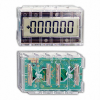
SSCUB-200/A Red Lion Controls, SSCUB-200/A Datasheet - Page 2

SSCUB-200/A
Manufacturer Part Number
SSCUB-200/A
Description
MODULE DIS COUNTER SSCUB200 DATA
Manufacturer
Red Lion Controls
Series
SUPER SUB-CUBr
Datasheet
1.DM-OSC-B03A.pdf
(8 pages)
Specifications of SSCUB-200/A
Count Rate
400kHz
Number Of Digits/alpha
6
Input Type
Voltage
Voltage - Supply
2.5 V ~ 6.0 V
Display Type
LCD Non-Backlit
Lead Free Status / RoHS Status
Lead free / RoHS Compliant
Output Type
-
Other names
RLC200A
SSCUB2
SSCUB200
SSCUB2
SSCUB200
DEVICE CONNECTIONS
COUNT (A) - CMOS, Schmidt Trigger; used as count or
COUNT (B) - CMOS, Schmidt Trigger; used as count or
RESET (R) - CMOS Schmidt trigger; counter is reset and
INHIBIT (I) - CMOS Schmidt trigger; all counting for all
LATCH (L) - CMOS Schmidt trigger; data on the display is
DP1, DP2, DP3 - CMOS level-sensitive; these inputs are
MS1, MS2, MS3, MS4, MS5, MS6 - CMOS level-sensitive;
OSC. - This input provides for connection of an external 2.4
V
V
* All other inputs must be tied to either V
CAUTION
handling to the same degree required by standard CMOS integrated circuits.
Units should be stored in the conductive packaging used to ship the devices.
Containers should be opened and units handled only on a conductive table
top by personnel wearing wrist strap grounding equipment. These devices
have the same protection circuits as standard CMOS devices to prevent
damage to inputs due to nominal over-voltage.
DD
SS
count control input, depending on the mode of operation
selected. It’s generally used as a count input. See Modes
of Operation for more details.
count control input, depending on the mode of operation
selected. It’s generally used as a count control input. See
Modes of Operation for more details.
held to zero when this pin is at a low level.
modes is inhibited when this input is at a low level. This
input is asynchronous with inputs “A” and “B”.
latched when this input is at a high level. This input has no
effect on the counting operations of the unit and is
asynchronous with inputs “A” and “B”
used for decimal point selection and leading zero blanking
selection. See Decimal Point and Leading Zero Blanking
Selection for more details.
these inputs are used for Mode Selection. These modes
include: Bi-Directional Counting, Quadrature Counting,
Anti-Coincidence Summing and Anti-Coincidence
Add/Subtract. See Modes of Operation for more details.
meg. resistor required by the on-board scan oscillator. The
oscillator operates at 240 Hz ±35% and has an internal
divider to provide 60 Hz back plane drive.
whichever is appropriate.
This device contains CMOS circuitry which requires special anti-static
- Common for D.C. Supply and Inputs.
- 2.5 to 6 VDC Supply
ELECTRICAL CHARACTERISTICS V
SYMBOL
fc max
T
I
fosc
V
I
DDQ
V
V
DD
I
RST
DD
IL
IH
IL
Input Leakage Current
Oscillator Frequency
Reset Pulse Width
Quiescent Current
Input High Voltage
Input Low Voltage
(50% Duty Cycle)
Count Frequency
Supply Current
Supply Current
Supply Voltage
PARAMETER
*
DD
or V
SS
,
MIN.
DD
400
250
200
100
2.5
4.5
3.9
20
10
= 5 V ±10% @ 20°C UNLESS OTHERWISE SPECIFIED
TYP.
0.01
240
3.0
0.9
25
60
10
2
MAXIMUM RATINGS (VOLTAGE REF. TO V
RATING
DC Supply Voltage
Input Voltage, All Inputs
Operating Temperature
Storage Temperature
MAX.
100
6.0
6.0
0.5
0.1
40
16
UNIT
VDC
VDC
VDC
KHz
KHz
KHz
KHz
KHz
µA
µA
µA
µA
Hz
µS
BLOCK DIAGRAM
TEST CONDITION
All Modes Except
Anti-Coincidence Modes
F
F
Anti-Coincidence Modes
Not Counting
V
X1, -10 & 100 Bidirectional Modes
X2, -5 & 50 Bidirectional Modes
X1, X2, -10, 100, 5 & 50 Quad. Mode
X4, -2.5 & 25 Quadrature Mode
Anti-Coincidence Modes
R EXT = 2.4M
C
C
SS
=10 KHz
=10 K
< V
SYMBOL
T
V
IN
T
V
STG
DD
A
I
< V
DD
-0.5 to (V
-0.5 to +6.5
-35 to +85
-35 to +85
VALUE
DD
+.5)
SS
)
UNIT
VDC
VDC
°C
°C


