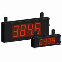
LD200400 Red Lion Controls, LD200400 Datasheet - Page 13

LD200400
Manufacturer Part Number
LD200400
Description
COUNTER 4 DIGIT 2.25" 120VAC RED
Manufacturer
Red Lion Controls
Series
LDr
Type
Counterr
Specifications of LD200400
Count Rate
35kHz
Number Of Digits/alpha
4
Input Type
Voltage
Voltage - Supply
11 V ~ 16 VDC, 85 V ~ 250 VAC
Display Type
LED Red
No. Of Digits / Alpha
4
Digit Height
57mm
Power Consumption
26VA
Counting Speed
25kHz
Operating Temperature Range
0°C To +50°C
Signal Input Type
Pulse
Character Size
2.25"
Ip/nema Rating
IP65 / NEMA 4X
Connection Type
Wire Leads
Dimensions
12"L×2.25"W×4"H
Display Digit Height
2.25 "
Function
Counter
Material, Casing
Aluminum
Number Of Digits
4
Primary Type
Electronic
Special Features
RS485/RS232 Communications
Termination
Terminal Block
Voltage, Supply
85 to 250/11 to 16 VAC/VDC
Counter Supply Voltage
85-250VAC/11-16VDC
Rohs Compliant
Yes
Lead Free Status / RoHS Status
Lead free / RoHS Compliant
Output Type
-
Lead Free Status / Rohs Status
RoHS Compliant part
Other names
RLC117
Parameters. These parameters are used to match the serial settings of the meter
with those of the host computer or other serial device.
Normally, the baud rate is set to the highest value that all of the serial
communications equipment is capable of transmitting and receiving.
other serial communications equipment on the serial link.
data word length. Set the parity bit to match that of the other serial equipment
on the serial link. The meter ignores parity when receiving data and sets the
parity bit for outgoing data. If parity is set to
to force the frame size to 10 bits.
and a value of zero can be used (RS232 applications). Otherwise, with multiple
bussed units, a unique address number must be assigned to each meter. The
node address applies specifically to RS485 applications.
in response to a Transmit Value command or a Block Print Request. Select
for a full print transmission, consisting of the meter address, mnemonics, and
parameter data. Select
parameter data only. This setting is applied to all the parameters selected in the
PRINT OPTIONS. (Note: If the meter address is 0, the address will not be sent
during a full transmission.)
5.5 MODULE 5 - S
Module 5 is the programming module for the Serial Communications
Set the baud rate to match that of other serial communications equipment.
Select either 7- or 8-bit data word length. Set the word length to match the
This parameter only appears when the Data Bit parameter is set to a 7-bit
Enter the serial node address. With a single unit, an address is not needed
This parameter determines the formatting of data transmitted from the meter
PAR
Baud Rate
5-SEr
bAUd
ABBREVIATED PRINTING
dAtA
Data Bit
for abbreviated print transmissions, consisting of the
METER ADDRESS
BAUD RATE
PARITY BIT
DATA BIT
to
Parity Bit
PAritY
, an additional stop bit is used
ERIAL
Addr
PARAMETER MENU
Address
Meter
C
OMMUNICATIONS
Abbreviated
13
Abbr
Printing
Request. A print request is also referred to as a block print because more than
one parameter can be sent to a printer or computer as a block.
in the print block. All active parameters entered as
transmitted during a block print. Parameters entered as
(
setting. For example, Counter B or Scale Factor B will only be sent if Counter
B is enabled (Dual Counter mode or batch count). Likewise, the Rate value will
not be sent unless the Rate Display is enabled.
Print Options selection list. This occurs without using the User Input terminal
Print Request function (Module 1), and without requiring any serial data request
commands. This makes the User Input available to perform other functions,
while still allowing the meter to output serial data.
operating mode, and pauses during programming mode.
directly to another LD meter(s), through the serial terminal block connections
(RS232 or RS485). No PC connection or additional software is required.
Copying program setttings eliminates or greatly reduces programming time
when multiple meters use identical, or very similar, settings for an application.
Copy Requirements:
To copy program settings from one meter to another requires the following:
1. Each meter must have the same software version. The version is displayed
2. Each meter receiving the program settings (receiver) must have the baud rate
This parameter selects the meter values transmitted in response to a Print
Selecting
The “Print All” (
Note: Inactive parameters will not be sent regardless of the print option
Selecting
The selected data is transmitted repeatedly every 1.5 seconds during normal
This parameter is used to copy all the program settings from one LD meter
during the meter power-up sequence, or by entering Code 50 in the Factory
Service Operations. (See Module 3 for details)
), without having to individually select each parameter in the sublist.
DISPLAY
Pr-OPt
Options
Print
displays a sublist for choosing the meter parameters to appear
causes the meter to automatically transmit serial data per the
AUTOMATIC DATA TRANSMIT
COPY PROGRAM SETTINGS
Counter A Count Load
P
Scale Factor A
Scale Factor B
DESCRIPTION
Rate Value
Counter B
Setpoint 1
Setpoint 2
Counter A
ARAMETERS
PRINT OPTIONS
) option selects all meter values for transmitting
AUtO
Automatic
Transmit
Data
FACTORY
SETTING
COPY
Program
Settings
Copy
(
in the sublist will be
will not be sent.
MNEMONIC
CTA
CTB
RTE
SFB
SP1
SP2
CLD
SFA
Pro
)


