LC4H-R4-DC24VS Panasonic Electric Works, LC4H-R4-DC24VS Datasheet - Page 23
LC4H-R4-DC24VS
Manufacturer Part Number
LC4H-R4-DC24VS
Description
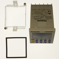
COUNTER DIGITAL 24VDC SCREW TERM
Manufacturer
Panasonic Electric Works
Series
LC4Hr
Datasheet
1.LC4H-R4-DC24V.pdf
(45 pages)
Specifications of LC4H-R4-DC24VS
Count Rate
30Hz or 5kHz Selectable
Number Of Digits/alpha
4
Input Type
Switch Closure or Transistor Switch
Output Type
Switch Closure
Voltage - Supply
12 V ~ 24 V
Display Type
LCD Red/Yellow
Lead Free Status / RoHS Status
Lead free / RoHS Compliant
Other names
255-1221
Available stocks
Company
Part Number
Manufacturer
Quantity
Price
Company:

Part Number:
LC4H-R4-DC24VS
Manufacturer:
Panasonic Electric Works
Quantity:
135


LC4H-W
Operation modes
1. Input mode
Q For the input mode, you can choose one of the following five modes.
W After the counter has been reset, setting 2 is displayed in the count-down mode. "0" appears instead in all other modes.
136
• Addition
• Subtraction
• Directive
• Independent
• Phase
Independent
Input mode
Subtraction
Directive
Addition
PHASE
DOWN
Phase
DIR
IND
UP
IN1 or IN2 works as an input block
(gate) for the other input.
IN1 is the counting input and IN2 is the
addition or subtraction directive input.
IN2 adds at L level and subtracts at H
level.
IN1 is addition input and IN2 is subtrac-
tion input.
Addition when the IN1 phase advances
beyond IN2, and subtraction when the
IN2 phase advances beyond IN1.
PHASE
DOWN
DIR
IND
UP
Operation
• Example where IN1 is the counting input and IN2 is the input block (gate).
• Example where IN2 is the counting input and IN1 is the input block (gate).
* “A” must be more than the minimum input signal width.
* “A” must be more than the minimum input signal width.
* IN1 and IN2 are completely independent, so there is no restriction on signal
* “B” must be more than the minimum input signal width.
timing.
Counting ( addition )
Counting ( subtraction )
Counting ( addition )
Counting ( subtraction )
I N 1
I N 2
I N 1
I N 2
Counting
I N 1
I N 2
Counting
I N 1
I N 2
Counting
I N 1
I N 2
*Minimum input signal width 30 Hz: 16.7 ms; 5 kHz: 0.1 ms
H
L
H
L
H
L
H
L
H
L
H
L
H
L
H
L
H
L
H
L
Blocked
Phase advance
Reset
Reset
0
Reset
0
Reset
Reset
0
n
0
0
n
Addition
n-1
1
1
1
A
2
2
n-1
1
A
1
Blocked
n-2
3
3
2
B
n-2
2
B
4
A A
A A
4
A A
2
3
n-3
Blocked
3
3
Subtraction
n-3
3
3
2
2
A A
1
n-4
2
4
A
n-3
1
3
0
Phase retard
A
n-2
1
2
1
2 1
n-1
Addition
2
1
n-1
1
*n: Set value 2
2
*n: Set value 2
Count UP
3
Count UP
0
n
0
n
0
3
4