H7CX-AWD1 DC12-24/AC24 Omron, H7CX-AWD1 DC12-24/AC24 Datasheet - Page 46
H7CX-AWD1 DC12-24/AC24
Manufacturer Part Number
H7CX-AWD1 DC12-24/AC24
Description
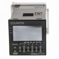
COUNTER DIGITAL 12VDC 2 STAGE
Manufacturer
Omron
Series
H7CXr
Datasheet
1.H7CX-AS_AC100-240.pdf
(63 pages)
Specifications of H7CX-AWD1 DC12-24/AC24
Count Rate
30Hz or 5kHz Selectable
Number Of Digits/alpha
6
Input Type
Voltage, Switch Closure, Transistor Switch
Output Type
Switch Closure
Voltage - Supply
12 V ~ 24 VDC, 24VAC
Display Type
LCD Programmable Color
Lead Free Status / RoHS Status
Lead free / RoHS Compliant
Other names
H7CXAWD1DC1224AC24
Z2741
Z2741


Connections
■ Block Diagram
■ I/O Functions
Note: Refer to page 56 for details on the hold function.
■ Terminal Arrangement
Note: 1. Terminals 4, 5, and 7 are all for the hold function. The func-
■ Input Circuits
Count and Hold Inputs
No-voltage Inputs (NPN Inputs)
Voltage Inputs (PNP Inputs)
IN
IN
Inputs
Outputs
Approx. 4.7 kΩ
2. Recommended wire: AWG 18 to 24 (Cross-sectional area:
tion is the same whichever terminal is connected. Terminals
4, 5, and 7 are not connected internally and so do not use
them for bridge wiring.
0.205 to 0.823 mm
1 kΩ
Input circuit
Sensor, etc.
(Basic insulation)
+14 V
External power supply
(−)
(+)
Output circuit
Internal
circuit
Internal
circuit
Count
Hold
Hold
Hold
Count
Hold
OUT
12 VDC
0 V
2
Internal control
circuit
), solid or twisted, copper or aluminum
(Basic
insulation)
3
4
2
(−)
5
1
6 7
11
(+)
10
8
(Basic insulation)
9
Power supply
circuit
Internal circuit
Display circuit
Key switch
circuit
Reads counting signals.
Holds the measurement value and outputs.
The hold indicator is lit during hold.
Outputs signals according to the specified output mode when a comparison value is reached.
OUT
H7CX-R
46