H7EC-NP Omron, H7EC-NP Datasheet - Page 11
H7EC-NP
Manufacturer Part Number
H7EC-NP
Description
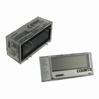
COUNT TOTALIZER LCD 1KHZ PCB MNT
Manufacturer
Omron
Series
H7ECr
Datasheet
1.Y92F-75.pdf
(33 pages)
Specifications of H7EC-NP
Count Rate
1kHz
Number Of Digits/alpha
8
Input Type
Switch Closure
Voltage - Supply
None Required (Battery Included)
Display Type
LCD Non-Backlit
Lead Free Status / RoHS Status
Lead free / RoHS Compliant
Output Type
-
Other names
H7EC-NP
H7ECNP
Z3009
H7ECNP
Z3009
Available stocks
Company
Part Number
Manufacturer
Quantity
Price
Company:

Part Number:
H7EC-NP
Manufacturer:
Omron Electronics Inc-IA Div
Quantity:
135


■ Characteristics
Note: Weight includes waterproof packing and flush mounting bracket.
■ Reference Value
Time accuracy
Insulation resistance
Dielectric strength
Impulse withstand
voltage
Noise immunity
Static immunity
Vibration resistance
Shock resistance
EMC
Degree of protection
Weight (see note)
Battery life
Item
Item
10 years min. with continuous input at
25°C (lithium battery)
±100 ppm (25°C)
100 MΩ min. (at 500 VDC) between
current-carrying metal parts and ex-
posed non-current-carrying metal
parts, and between the backlight pow-
er supply and timer input terminals/re-
set terminals for backlight models
1,000 VAC, 50/60 Hz for 1 min between
current-carrying metal parts and ex-
posed non-current-carrying metal
parts and between the backlight power
supply and timer input terminals/reset
terminals for backlight models
4.5 kV between current-carrying termi-
nal and exposed non-current-carrying
metal parts
Square-wave noise generated by noise simulator (pulse width: 100 ns/1 µs, 1-ns rise)
±600 V (Between timer input terminals/
Between reset terminals)
±480 V (Between the backlight power
supply terminals for backlight models)
±8 kV (malfunction)
Malfunction: 0.15-mm single amplitude at 10 to 55 Hz for 10 min each in 3 directions
Destruction: 0.375-mm single amplitude at 10 to 55 Hz for 2 hrs each in 3 directions
Malfunction: 200 m/s
Destruction: 300 m/s
(EMI)
Emission Enclosure:
(EMS)
Immunity ESD:
Immunity RF-interference from AM Radio Waves:
Immunity RF-interference from Pulse-modulated Radio Waves:
Immunity Conducted Disturbance: EN61000-4-6: 10 V (0.15 to 80 MHz) (level 3)
Immunity Burst:
Front panel:
Terminal block: IP20
No-backlight model: Approx. 60 g
Backlight model: Approx. 65 g
H7ET-NV@-H@
H7ET-NV@-@
Value
IP66, NEMA4 with waterproof packing
2
2
3 times each in 6 directions
3 times each in 6 directions
EN61326
EN55011 Group 1 class B
EN61326
EN61000-4-2: 4 kV contact discharge (level 2)
EN61000-4-3: 10 V/m (80 MHz to 1 GHz) (level 3)
EN61000-4-3: 10 V/m (900 MHz ± 5 MHz) (level 3)
EN61000-4-4: 2 kV power line (level 3)
The battery life is calculated according to the conditions in the left column and
therefore is not a guaranteed value. Use these value as reference for mainte-
nance or replacement.
100 MΩ min. (at 500 VDC) between
current-carrying metal parts and ex-
posed non-current-carrying metal
parts and between timer input termi-
nals and reset terminals
3,700 VAC, 50/60 Hz for 1 min between
timer input terminals and exposed non-
current-carrying metal parts
2,200 VAC, 50/60 Hz for 1 min between
reset terminals and exposed non-cur-
rent-carrying metal parts and between
timer input terminals and reset termi-
nals
4.5 kV between current-carrying termi-
nal and exposed non-current-carrying
metal parts
3 kV between timer input terminals and
reset terminals
±1.5 kV (Between timer input termi-
nals)
±500 V (Between reset terminals)
Approx. 60 g
H7ET-NFV@-@
8 kV air discharge (level 3)
2 kV I/O signal line (level 4)
Note
100 MΩ min. (at 500 VDC) between
current-carrying metal parts and ex-
posed non-current-carrying metal
parts
1,000 VAC, 50/60 Hz for 1 min between
current-carrying metal parts and ex-
posed non-current-carrying metal
parts
4.5 kV between current-carrying termi-
nal and exposed non-current-carrying
metal parts
±500 V (Between timer input terminals/
Between reset terminals)
Approx. 60 g
H7ET-N@-@
New H7ET
11