SCUB1-000/A Red Lion Controls, SCUB1-000/A Datasheet - Page 3
SCUB1-000/A
Manufacturer Part Number
SCUB1-000/A
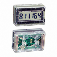
Description
COUNTER DISPLAY SCUB1000 + DATA
Manufacturer
Red Lion Controls
Series
SUB-CUBr
Datasheet
1.HWK-40-000A.pdf
(4 pages)
Specifications of SCUB1-000/A
Count Rate
500kHz
Number Of Digits/alpha
6
Input Type
Voltage
Voltage - Supply
2.5 V ~ 6.0 V
Display Type
LCD Non-Backlit
Lead Free Status / RoHS Status
Lead free / RoHS Compliant
Output Type
-
Other names
RLC1000
SCUB-1000
SCUB-1000A
SCUB1
SCUB1-000
SCUB-1000
SCUB-1000A
SCUB1
SCUB1-000


TYPICAL APPLICATIONS
COUNT & CONTROL FROM REMOTE INPUTS
remote “off-board” signal sources are used. This illustration shows a SUB-
CUB being used in an elementary counting application to depict some of the
buffering methods that can be used.
resistance is split into two 10 K resistors, with a filter cap to eliminate spurious
counts due to electrical interference pickup. The filter network will allow count
rates to 10 KHz with Symetrical +5 V input count pulses. The 4.7 K across the
input would not be required if the circuit supplying the count pulses has a low
off-state output impedance.
consisting of two 47 K resistors and a 0.01 μf capacitor.
FREQUENCY, SPEED, FLOW, SPEED-RATIO,
PERIOD & CYCLE TIME INDICATIONS
coordination required for frequency or time-period readouts.
displayed, is applied to the CLK-A input, (the inverter, in the CLK-A input,
causes the SUB-CUB to increment on the positive going edge of CLK-A pulses
and can be onitted if negative edge incrementing is satisfactory). The CLK-B
input is supplied with standard time-base pulses whose period determines the
measuring time. For frequency measurement, this time is 1 second so CLK-B
input would be supplied with 1 pulse/sec. from a crystal clock or line-reference
divider. At the positive going edge of each CLK-B pulse, the first monostable
opens the SUB-CUB latch momentarily to update the display to the count
existing at that instant of time. Immediately after the latch closes, freezing the
updated count on the display, the internal counter in the SUB-CUB display is
reset to zero in preparation for a new counting cycle. Thus, at the end of each
measuring time interval the SUB-CUB display is updated to readout the number
of pulses received during the period, while it is accumulating new counts for the
next update.
B) input with a pulse train related to the second variable (or denominator) of
the ratio. Normally this pulse train is divided by 10, 100, or 1000 before being
applied to the CLK-B input to provide a higher resolution reading.
interchanged. CLK-A input is now supplied with standard Clock Pulses, say 1
Hz to readout in seconds, while the pulse train whose period is being measured
is applied to the CLK-B input.
PULSE WIDTH OR DWELL-TIME READOUT
function at two different times.
increments, is applied to the CLK-A input. For example if readout in seconds is
desired, CLK-A would receive 1 pulse/second, or 1 Hz The pulse whose width
is to be measured is applied to CLK-B input. At the positive going edge of the
CLK-B pulse, the first monostable momentarily resets the SUB-CUB internal
counter to zero, and it then begins accumulating counts from the CLK-A time
reference pulses. At the conclusion of the CLK-B pulse, the negative going
edge momentarily opens the SUB-CUB display latch, and the number of time-
reference pulses that have been counted, since reset, is latched on the display to
provide a direct readout of CLK-B pulse-width.
Inputs to SUB-CUB are CMOS inputs and must be adequately buffered if
The Count Input is buffered by the NPN Transistor input circuit. The base
The Remote Button-actuated Reset input is buffered by a simple RC circuit
This circuit uses a dual monostable I.C. to generate the proper latch and reset
When frequency readout is desired, the pulse train whose frequency is to be
Frequency ratio can be displayed by replacing the standard time-base (CLK-
For period or cycle-time indication, CLK-A and B inputs are simply
This circuit also uses two monostables, however for pulse-width readout they
A train of standard clock pulses, whose period determines the readout
COUNT
INPUTS
3
CLK-B
CLK-A
CLK-B
CLK-A
CLK-A
CLK-B
L-LATCH
R-RESET
10K
+5VDC SUPPLY
.001 µf
.001 µf
14
12
11
14
12
11
.005
1/2-4528
A
B
1/2-4528
A
B
10K
+5V
+5V
15
15
COMMON
µf
8
8
Q
Q
9
9
.001 µf
REMOTE
.001 µf
RESET
47K
2
4
5
1/2-4528
A
B
3
2
4
5
1/2-4528
A
B
16 13
1
3
Q
16 13
1
.01
7
Q
µf
7
TIME BASE
OR PERIOD
V
V
V
V
V
V
DD
R
C
SS
DD
R
C
T
L
T
L
SS
DD
T
R
C
L
SS