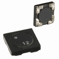
Low-Profile Dual Winding Shielded Inductor/Transformer
SDQ Series
Description
• 125°C maximum total temperature operation
• Dual winding inductors that can be used as either a single inductor, or
• Windings can be connected in series or parallel, offering a broad range
• Current range from 6.43 to 0.063 Amps
• Inductance range from 0.47µH to 4.03mH
(1) Test Parameters: 100kHz,.0.25 Vrms 0.0Adc
(2) I rms : DC current for approximately ΔT of 40°C without core loss. It is recommended that the
(3) I sat : Peak current for approximately 30% rolloff @20°C
(4) DCR limits @20°C
06-13-08
P P a a r r t t
N N u u m m b b e e r r
SDQ12-R47-R
SDQ12-1R0-R
SDQ12-1R5-R
SDQ12-2R2-R
SDQ12-3R3-R
SDQ12-4R7-R
SDQ12-6R2-R
SDQ12-8R2-R
SDQ12-100-R
SDQ12-150-R
SDQ12-220-R
SDQ12-330-R
SDQ12-470-R
SDQ12-680-R
SDQ12-820-R
SMD Device
temperature of the part not to exceed 125°C. Derating is necessary for AC currents
in coupled inductor/transformer applications (1:1 turns ratio)
of inductance and current ratings
SB-BU08352
I I n n d d u u c c t t a a n n c c e e
R R a a t t e e d d
0.47
( ( µ µ H H ) )
1.5
2.2
3.3
4.7
6.2
8.2
10
15
22
33
47
68
82
1
M M a a r r k k i i n n g g
P P a a r r t t
M
A
B
C
D
E
G
H
K
N
O
P
F
J
L
0.49±30%
O O C C L L
± ± 2 2 0 0 % %
15.21
22.09
32.49
47.61
68.89
82.81
0.81
1.69
2.25
3.61
4.41
6.25
8.41
9.61
( ( µ µ H H ) )
( ( 1 1 ) )
I I r r m m s s
0.868
0.831
0.658
0.548
0.439
0.401
0.326
0.309
A A m m p p s s
2.78
2.49
1.69
1.60
1.28
1.12
1.02
( ( 2 2 ) )
P P a a r r a a l l l l e e l l R R a a t t i i n n g g s s
0.981
0.779
0.647
0.533
0.441
0.366
0.334
I I s s a a t t
A A m m p p s s
4.34
3.38
2.34
2.03
1.60
1.45
1.22
1.05
( ( 3 3 ) )
( ( Ω Ω ) ) t t y y p p . .
0.0325
0.0403
0.0870
0.0977
0.1527
0.1990
0.2387
0.3318
0.3620
0.5766
0.8332
D D C C R R
1.29
1.55
2.36
2.62
• Ferrite shielded, low EMI
• Ferrite core material
• 500Vdc isolation between windings
• RoHS compliant
Applications
• As a transformer: SEPIC, flyback
• As an inductor: Buck, boost, coupled inductor
• Digital cameras, CD players, cellular phones, and PDA’s
• PCMCIA cards
• GPS systems
Environmental Data
• Storage temperature: -40°C to +125°C
• Operating temperature range: -40°C to +125°C
• Solder reflow temperature: 260°C max. for 10 seconds max.
Packaging
• Supplied in tape and reel packaging, SDQ12-3800, SDQ25-2900 parts
(5) Applied Volt-Time product (V-µS) across the inductor at 100kHz necessary to generate a core loss equal
Part Number Definition:
SDQ12-XXX-R
SDQ12 = Product code and Size
XXX = Inductance in uH, R = Decimal point
If no R is present, third character = # of zeros.
-R suffix indicated RoHS compliant
( ( 4 4 ) )
to 10% of the total losses for a 40°C temperature rise. Derating of the I rms is required to
prevent excessive temperature rise.
(Range is application specific).
per reel, 13” diameter reel
Page 1 of 4
V V o o l l t t s s
10.15
10.85
13.65
16.45
19.95
24.15
29.05
31.85
µ µ - - S S e e c c
2.45
3.15
4.55
5.25
6.65
7.35
8.75
t t y y p p . .
( ( 5 5 ) )
1.96±30%
± ± 2 2 0 0 % %
O O C C L L
14.44
17.64
25.00
33.64
38.44
60.84
88.36
130.0
190.4
275.6
331.2
3.24
6.76
9.00
( ( µ µ H H ) )
( ( 1 1 ) )
Data Sheet: 4339
I I r r m m s s
0.847
0.800
0.640
0.560
0.512
0.434
0.416
0.329
0.274
0.220
0.201
0.163
0.154
A A m m p p s s
1.39
1.25
( ( 2 2 ) )
S S e e r r i i e e s s R R a a t t i i n n g g s s
0.800
0.724
0.608
0.524
0.490
0.390
0.323
0.267
0.220
0.183
0.167
I I s s a a t t
A A m m p p s s
2.17
1.69
1.17
1.01
( ( 3 3 ) )
D D C C R R Ω Ω ( ( 4 4 ) )
0.1298
0.1611
0.3481
0.3908
0.6106
0.7959
0.9548
10.49
1.33
1.45
2.31
3.33
5.18
6.21
9.43
t t y y p p . .
V V o o l l t t s s
µ µ - - S S e e c c
4.90
6.30
9.10
10.5
13.3
14.7
17.5
20.3
21.7
27.3
32.9
39.9
48.3
58.1
63.7
t t y y p p . .
( ( 5 5 ) )