41F Cinch Connectors, 41F Datasheet - Page 198
41F
Manufacturer Part Number
41F
Description
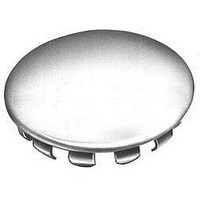
PLUG BUTTON .875" HOLE
Manufacturer
Cinch Connectors
Type
Body Plugr
Datasheet
1.41C.pdf
(282 pages)
Specifications of 41F
Color
Natural
Hole Diameter
0.875" (22.23mm)
Flange Diameter
1.062" (26.97mm)
Rohs Compliant
YES
Lead Free Status / RoHS Status
Lead free / RoHS Compliant
Panel Thickness
-
Lead Free Status / RoHS Status
Lead free / RoHS Compliant
Available stocks
Company
Part Number
Manufacturer
Quantity
Price
Company:

Part Number:
41F-1Z-C2-1
Manufacturer:
HGF
Quantity:
6
Company:
Part Number:
41FVX-RSM1-GSAN-G-ETF(S)
Manufacturer:
SHUN
Quantity:
994
Company:
Part Number:
41FXW-RSMI-G-G-TB
Manufacturer:
N/A
Quantity:
320


Ordering Information
Dura-Con
High Reliability
All-Plastic
Contact Arrangements
(Face view of pin insulator)
(Use reverse order for socket)
** - See p. 5-12 for std. hardware dims. See p. 5-13 for non-std. hardware & p. 5-31 for Mil spec. hardware both sold separately.
***- Length Tolerance: solid wire = ± 3/32”, standard wire = ± 1/4”.
* - Indicates Cinch std. option.
Cinch Dura-Con D Connector
Insulator Type
*D = Thermoplastic
Glass Reinforced
Mounting Type
*A = Screw Mount Flange
No. of Contacts
9, 15, 21, 25, 31, 37, 51
Contact Type
P – Pin (Plug)
S – Socket (Receptacle)
Wire Size in AWG
5 = 25 AWG Solid Copper
6 = 26 AWG Stranded
S = Solder Cup (Skip to Mounting Hardware)
Wire Type
E = MIL-W-16878/4, 7 Strand
C = Solid Copper - Uninsulated
(
Consult factory for non-standard wire types)
DC D A 37 P 6 E 2 -18.0 K
.050" (1.27mm) Density
Solder Cup/Wire
D-Microminiature
5-5
Call Toll Free: 1 (800) 323-9612
Mounting Hardware**
B = No Hardware
F = Float Mount
R = Reverse Float Mount
K = Jackscrew (Standard)
L = Jackscrew (Low Profile)
P = Jackpost, MIL-C-83513/5-07
Lead Length in inches***
00.5 Solid copper wire only
01.0 Solid copper wire only
02.0 Solid copper wire only
18.0 Stranded wire only
24.0 Stranded wire only
36.0 Stranded wire only
48.0 Stranded wire only
Insulation
Color or Wire Finish
*2 = Yellow (Stranded Wire)
*4 = Gold-Plated (Solid Wire Only)
*5 = Color Coded Per MIL-Std. (681)
System 1. (Stranded Wire Only)
1 = White
3 = Tin-Plated
Related parts for 41F
Image
Part Number
Description
Manufacturer
Datasheet
Request
R

Part Number:
Description:
Standard Card Edge Connectors CINCH BLK CARD GUIDE
Manufacturer:
Cinch Connectors

Part Number:
Description:
Automotive Connectors 18 Pos Black
Manufacturer:
Cinch Connectors
Part Number:
Description:
Automotive Connectors 30 Pos Black
Manufacturer:
Cinch Connectors
Part Number:
Description:
Automotive Connectors 30 Pos Black mates only w/ 60 Pin
Manufacturer:
Cinch Connectors
Part Number:
Description:
D-Subminiature Connectors 25C PLG S/CUP BASIC-D SERIES
Manufacturer:
Cinch Connectors

Part Number:
Description:
D-Subminiature Connectors 9C 2PC PLSTC BCKSHLL
Manufacturer:
Cinch Connectors

Part Number:
Description:
TERMINAL BLOCK JUMPER TYPE F
Manufacturer:
Cinch Connectors
Datasheet:
Part Number:
Description:
D-Subminiature Connectors MCHNED PIN 20-24AWG
Manufacturer:
Cinch Connectors
Datasheet:
Part Number:
Description:
Terminal Block,4 Contacts,0.44 Pitch
Manufacturer:
Cinch Connectors
Datasheet:

Part Number:
Description:
Terminal Block,8 Contacts,0.375 Pitch
Manufacturer:
Cinch Connectors
Datasheet: