DEA252450BT-7046A1 TDK Corporation, DEA252450BT-7046A1 Datasheet
DEA252450BT-7046A1
Specifications of DEA252450BT-7046A1


Related parts for DEA252450BT-7046A1


DEA252450BT-7046A1 Summary of contents
Page 1
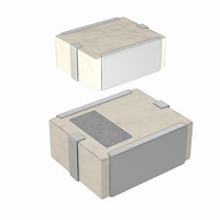
... Top View 2.5±0 1.8±0.15 View Bottom Unbalanced Input 50 ohm (Nominal) DC feed port Note: All specifications are subject to change and are not guaranteed. (Balance output type) DEA252450BT-7046A1 For Bluetooth 1.0 max. 5 2.0±0.2 4 Unit : mm 0.4±0.15 0.8±0.10 0.15 +0.15/-0. Feb ...
Page 2
ELECTRICAL CHARACTERISTICS Parameter Frequency Range (Pass Band) Unbalanced Port Characteristics Impedance Balanced Port Characteristics Impedance Unbalanced Port Return Loss Insertion Loss (Pass Band) 880 - 960 MHz 1710 - 1880 MHz Attenuation 1880 - 1990 MHz 4800 - 5000 MHz ...
Page 3
... FREQUENCY RESPONSE DEA252450BT-7046A1 Unbalance Side : Z= 50 ohm Balance Side : Z= 34+j72.2 ohm Log MAG REF 0.0dB SCALE 5.0dB ATTENUATION -10 -15 -20 -25 4 -30 5 -35 -40 3 -45 -50 2 -55 -60 -65 1 -70 500 1500 2500 3500 4500 5500 Log MAG REF 0.0dB SCALE 5.0dB - -15 -20 -25 Unbalanced Port RETURN LOSS ...
Page 4
RECOMMENDED PCB PATTERN * * Coplanar waveguide (Line width and Gap of Line to GND designed to match 50ohm characteristic impedance , depending on PCB material and thickness. Note: All specifications are subject to change and are not ...