2450BP15B100E Johanson Technology Inc, 2450BP15B100E Datasheet - Page 41
2450BP15B100E
Manufacturer Part Number
2450BP15B100E
Description
FILTER BANDPASS 2.4GHZ
Manufacturer
Johanson Technology Inc
Specifications of 2450BP15B100E
Frequency
2.45GHz Center
Bandwidth
100MHz
Filter Type
Bandpass
Insertion Loss
2.2dB
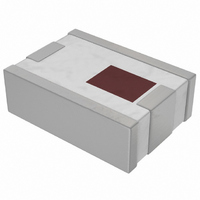
Package / Case
0805 (2012 Metric)
Mounting Type
Surface Mount
Frequency Range
2.4GHz To 2.5GHz
Return Loss
9.5dB
Bandpass Insertion Loss Max
2.2dB
Attenuation @ Reject Band Min
10dB
Filter Case
0805
Termination Type
SMD
Rohs Compliant
Yes
Lead Free Status / RoHS Status
Lead free by exemption / RoHS Compliant
Ripple
-
Other names
2450BP15B100
712-1078-2
712-1078-2


Johanson Technology has the capability to produce a wide range of application specific components for
wireless communication such as Diplexer Switch, VCO, PA and highly integrated RF modules using LTCC (Low
Temperature Co-fired Ceramic) technology. We offer extensive expertise using an internally developed LTCC
tape system.
C
Design Rules
(A) Via Hole Dia
(B) Via Cover Dot Dia
(C) Via Center Spacing
(D) Via Cover Dot Edge to Line Edge
(E) Line Width
(F) Line to Line Spacing
(G) Line Center Spacing
(H) Outside Edge to Via Center
(I) Line Over Outside Edge for Cutting
(J) Outside Edge to Line Clearance
(M) Buried Ground Plane Spacing
(N) Feed Thru Spacing
Substrate Thickness
Number of Layers
Dielectric Constant (@ 3GHz)
Dielectric Loss (@ 3GHz)
TCE (25-300°C) (ppm/°C)
USTOM
LTCC Tape Characteristics
LTCC M
ODULE
F
OUNDRY
≥ 0.20 (for 0.07 via)
Standard (mm)
www.johansontechnology.com
www.johansontechnology.com
S
0.125, 0.180
≥ Via + 0.03
0.5 to 1.6
ERVICE
Up to 20
> 0.10
≥ 0.10
≥ 0.10
≥ 0.18
≥ 0.15
> 0.05
> 0.10
0.33%
0.10
0.15
JTI
7.5
4.7
≥ 0.18 (for 0.05 via)
Advanced (mm)
≥ Via + 0.02
0.06 (min.)
0.3 to 2.4
Up to 30
≥ 0.135
> 0.08
≥ 0.05
≥ 0.08
≥ 0.13
> 0.05
> 0.10
0.10
0.10
41
Related parts for 2450BP15B100E
Image
Part Number
Description
Manufacturer
Datasheet
Request
R

Part Number:
Description:
Manufacturer:
Johanson Technology Inc
Datasheet: