NZF220TT1G ON Semiconductor, NZF220TT1G Datasheet
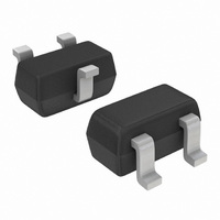
IC FILTER EMI SINGLE ESD SC75-3

NZF220TT1G

Manufacturer Part Number
NZF220TT1G
Description
IC FILTER EMI SINGLE ESD SC75-3
Manufacturer
ON Semiconductor
Datasheet

Specifications of NZF220TT1G

Resistance (ohms)
110
Capacitance
10pF
Package / Case
SC-75-3, SOT-416, EMT3, 3-SSMini
Resistance In Ohms
110
Product
EMI Filters
Impedance
50 Ohms
Maximum Dc Current
1 uAmps
Maximum Dc Resistance
110 Ohms
Operating Temperature Range
0 C to + 150 C
Shielding
Unshielded
Test Frequency
220 MHz
Lead Free Status / RoHS Status
Lead free / RoHS Compliant
Power (watts)
-
Tolerance
-
Lead Free Status / Rohs Status
Lead free / RoHS Compliant
Other names
NZF220TT1GOS
NZF220TT1GOS
NZF220TT1GOSTR

Available stocks

Company
Part Number
Manufacturer
Quantity
Price
Part Number:
NZF220TT1G
Manufacturer:
ON
Quantity:
3 000
NZF220TT1
EMI Filter with ESD
Protection
Features:
Benefits:
Applications:
Stresses exceeding Maximum Ratings may damage the device. Maximum
Ratings are stress ratings only. Functional operation above the Recommended
Operating Conditions is not implied. Extended exposure to stresses above the
Recommended Operating Conditions may affect device reliability.
1. All diodes under power
MAXIMUM RATINGS
© Semiconductor Components Industries, LLC, 2006
March, 2006 − Rev. 3
Peak Power Dissipation (Note 1)
Maximum Junction Temperature
Electromagnetic Interference
“Ideal” Low Pass Filtering Response
EMI/RFI Bi−directional “Pi” Low−Pass Filters
ESD Protection Meets IEC61000−4−2
Diode Capacitance: 7 − 10 pF
Zener/Resistor Line Capacitance: 22 ± 20% pF
Low Zener Diode Leakage: 1 mA Maximum
Zener Breakdown Voltage; 6 − 8 Volts
Pb−Free Package is Available
Designed to Suppress EMI/RFI Noise in Systems Subjected to
Small Package Size Minimizes Parasitic Inductance, Thus a More
Cellular Phones
Communication Systems
Computers
Portable Products with Input/Output Conductors
8
×
20 ms Pulse
Rating
Symbol
P
T
PK
J
Value
150
14
1
Unit
°C
W
†For information on tape and reel specifications,
NZF220TT1
NZF220TT1G
including part orientation and tape sizes, please
refer to our Tape and Reel Packaging Specification
Brochure, BRD8011/D.
CASE 463
(Note: Microdot may be in either location)
*Date Code orientation may vary depending
Device
STYLE 4
3
upon manufacturing location.
SC−75
1
1
ORDERING INFORMATION
X6
M
G
CIRCUIT DESCRIPTION
2
http://onsemi.com
(Pb−Free)
Package
= Device Code
= Date Code*
= Pb−Free Package
SC−75
SC−75
Publication Order Number:
3
MARKING
DIAGRAM
1
3000/Tape & Reel
3000/Tape & Reel
X6 M G
Shipping
G
NZF220TT1/D
2

Related parts for NZF220TT1G

NZF220TT1G Summary of contents

Page 1

... ORDERING INFORMATION Device Package Shipping NZF220TT1 SC−75 3000/Tape & Reel NZF220TT1G SC−75 3000/Tape & Reel (Pb−Free) †For information on tape and reel specifications, including part orientation and tape sizes, please refer to our Tape and Reel Packaging Specification Brochure, BRD8011/D. ...

Page 2

... Use the longest rise/fall times possible for all digital signals Reducing Noise at the Receiver • Filter all I/O signals entering the unit • Locate the I/O filters as close as possible to the connector Minimizing Noise Coupling • Use multilayer PCBs to minimize power and ground inductance • ...

Page 3

Frequency Response Specification TG OUTPUT RF INPUT TEST BOARD NZF220T Figure 1. Measurement Conditions −6.3 −50 1 FREQUENCY (MHz) Figure 2. Typical EMI Filter Response (50 W Source and 50 W Lead Termination) http://onsemi.com TRACKING GENERATOR 50 W ...

Page 4

... ON Semiconductor Soldering and Mounting Techniques Reference Manual, SOLDERRM/D. N. American Technical Support: 800−282−9855 Toll Free USA/Canada Japan: ON Semiconductor, Japan Customer Focus Center 2−9−1 Kamimeguro, Meguro−ku, Tokyo, Japan 153−0051 Phone: 81− ...

Related keywords