B84266A21E13 EPCOS Inc, B84266A21E13 Datasheet
B84266A21E13
Specifications of B84266A21E13


Related parts for B84266A21E13


B84266A21E13 Summary of contents
Page 1
... Filters for Control Lines Filter für Steuerleitungen Four-line filters 4 A Stopband attenuation GHz Overview B84264: Single-stage, insertion loss = 100 dB from 150 kHz B84266: Three-stage, insertion loss = 100 dB from 14 kHz Features General-purpose use through design with separate lines without intercoupling Use of single chokes ...
Page 2
... Filters for Control Lines Circuit diagrams B84264 B84266 1 1‘ 2 2‘ 3 3‘ 4 4‘ SSB1787-4 SSB1788-C-E 64 12/01 B84264 B84266 1‘ 2‘ 3‘ 4‘ ...
Page 3
... Filters for Control Lines Insertion loss (typical values Measurement circuit 50 Filter ~ ~ ~ [dB B84264 (single-stage) 120 dB Measurement limit e 100 GHz SSB1693-7-E B84266 (three-stage) SSB1789-K-E 120 dB e 100 12/01 B84264 B84266 SSB1790-N-E Measurement limit GHz ...
Page 4
... Filters for Control Lines General technical data Rated voltage V R Rated current I R Rated frequency f R Max. admissible overcurrent I over Test voltages V T Voltage drop/phase V DC resistance R max Power dissipation P D Climatic category Mechanical version Characteristics and ordering codes I Mecha max ...
Page 5
... Filters for Control Lines Dimensional drawing 1 B84264-A21-E11 435 1 Input end: Cable gland Shielded end: Connecting flange in base with RF gasket. Matching welded flange for shielded wall: B83208-A-Z808 (must be ordered separately) Fixing dimensions (168) 10 250 90 Welded flange B83208–A–Z808 SSB1792-5-E (Welded flange must be ordered separately) ...
Page 6
... Filters for Control Lines Dimensional drawing 2 B84264-C21-E11 435 1 Input end: Cable gland Shielded end: Cable gland PG 21; 2 matching connector fitting, width 25 mm, ordering code B84298-A42-L*** (must be ordered separately) Fixing dimensions 1) 248 250 168 connector fitting with 25 mm width is used (must be ordered separately, ordering code B84298-A42-L12) ...
Page 7
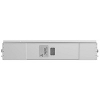
... Filters for Control Lines Dimensional drawing 3 B84266-A21-E13 649 Input end: Cable gland PG 21 Fixing dimensions (168) 380 90 10 SSB1796-3-E Welded flange B83208–A–Z808 (Welded flange must be ordered separately) Shielded end SSB1795-U-E 69 12/01 B84264 B84266 ...
Page 8
... Filters for Control Lines Dimensional drawing 4 B84266-C21-E13 649 1 Input end: Cable gland Shielded end: Cable gland PG 21; 2 matching connector fitting, width 25 mm, ordering code B84298-A42-L*** (must be ordered separately) Fixing dimensions 380 168 connector fitting with 25 mm width is used (must be ordered separately, ordering code B84298-A42-L12) ...
Page 9
Herausgegeben von EPCOS AG Marketing Kommunikation, Postfach 80 17 09, 81617 München, DEUTSCHLAND EPCOS AG 2002. Alle Rechte vorbehalten. Vervielfältigung, Veröffentlichung, Verbreitung und Verwertung dieser Broschüre und ihres Inhalts ohne ausdrückliche Genehmigung der EPCOS AG nicht gestattet. Mit den ...