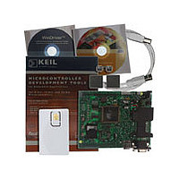
AT89STK03 Atmel, AT89STK03 Datasheet - Page 15

AT89STK03
Manufacturer Part Number
AT89STK03
Description
Manufacturer
Atmel
Datasheet
1.AT89STK03.pdf
(38 pages)
Specifications of AT89STK03
Lead Free Status / RoHS Status
Supplier Unconfirmed
Table 3-1. Programming the MCU with FLIP
3.1.2
AT89STK-03 Hardware User Guide
Interface
RS232C
Execution mode
Perform the following actions
DEMO BOARD CONFIGURATION
- Set the POWER switch in OFF position
- Remove any USB cable connected to demoboard
- Remove any E2P present on DIP socket
- Configure the power jumper accordingly to power source wich supplies the demo board
- Connect a RS232C cable between demo board and PC
- Set the POWER switch in ON position
--> Result : PWR ON and ALE leds are switched on
--> Trouble shooting : check if 8 Mhz quartz is correctly fitted
PROGRAMMING PART
- Run FLIP
- Select part at8xc5122 for FLIP 1.8.8 or part at8xc5122_dpw for FLIP 2.x.x
- Select a RS232C communication
- Establish a serial communication with the appropriate COM number and a baudrate comprised
between 1200 and 38400 .
---> Results :
- Select Erase, Blank check, Program and Verify options if part is running for the first time, otherwise
just select Program.
- Load the code file (Intel hex format) into FLIP buffer
- Click on Run button
- Click on Start Application button
- Bootloader Vers = 1.1.2
- DeviceBoot Ids = 02 00
- Start Application button becomes red
When the E2PROM is connected to ports P4.2 and P4.3 or P3.6 and P3.7, the boot-
loader works automatically in execution mode. At reset, it transfers the code from the
E2PROM to the internal CRAM (volatile program memory) and execute it. The E2PROM
must contain a valid code. As the bootloader does not support E2PROM programming
functions, the E2PROM must be programmed by external programmer or by a specific
code which is programmed in CRAM and which behaves as a bootloader. This code
programs the E2PROM by the code received from FLIP.
Comments
Part Programming
7609B–SCR–11/06
3-13


