HFA04SD60SPBF Vishay, HFA04SD60SPBF Datasheet
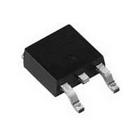
FAST DIODE, 4A, 600V, TO-220AC

HFA04SD60SPBF

Manufacturer Part Number
HFA04SD60SPBF
Description
FAST DIODE, 4A, 600V, TO-220AC
Manufacturer
Vishay

Specifications of HFA04SD60SPBF

Rectifier Type
Switching Diode
Configuration
Single
Peak Rep Rev Volt
600V
Avg. Forward Curr (max)
4
Rev Curr
3uA
Peak Non-repetitive Surge Current (max)
25A
Forward Voltage
2.2@8AV
Operating Temp Range
-55C to 150C
Package Type
DPAK
Rev Recov Time
42ns
Operating Temperature Classification
Military
Mounting
Surface Mount
Pin Count
2 +Tab
Repetitive Reverse Voltage Vrrm Max
600V
Forward Current If(av)
4A
Forward Voltage Vf Max
2.2V
Reverse Recovery Time Trr Max
42ns
Forward Surge Current Ifsm Max
25A
Diode Type
Fast Recovery
Product
Ultra Fast Recovery Rectifier
Reverse Voltage
600 V
Forward Voltage Drop
2.2 V at 8 A
Recovery Time
42 ns
Forward Continuous Current
4 A
Max Surge Current
25 A
Reverse Current Ir
3 uA
Mounting Style
SMD/SMT
Package / Case
DPAK
Maximum Operating Temperature
+ 150 C
Minimum Operating Temperature
- 55 C
Lead Free Status / RoHS Status
Compliant
Lead Free Status / RoHS Status
Lead free / RoHS Compliant, Compliant
Document Number: 94034
Revision: 13-Jan-11
PRODUCT SUMMARY
ABSOLUTE MAXIMUM RATINGS
PARAMETER
Cathode to anode voltage
Maximum continuous forward current
Single pulse forward current
Repetitive peak forward current
Maximum power dissipation
Operating junction and storage temperatures
ELECTRICAL SPECIFICATIONS (T
PARAMETER
Breakdown voltage,
blocking voltage
Forward voltage
See fig. 1
Maximum reverse
leakage current
Junction capacitance
Series inductance
D-PAK (TO-252AA)
Diode variation
Package
T
V
t
J
rr
I
F
F(AV)
V
max.
at I
typ.
R
F
HEXFRED
DiodesAmericas@vishay.com, DiodesAsia@vishay.com,
SYMBOL
For technical questions within your region, please contact one of the following:
V
C
V
V
L
I
BR
R
R
F
S
T
,
D-PAK (TO-252AA)
N/C
®
I
I
I
I
V
T
V
Measured lead to lead 5 mm from package body
Single die
1
R
F
F
F
R
J
R
150 °C
= 4 A
= 8 A
= 4 A, T
Ultrafast Soft Recovery Diode, 4 A
= 100 μA
600 V
17 ns
1.8 V
= 125 °C, V
= V
= 200 V
4 A
J
2, 4
R
= 25 °C unless otherwise specified)
Anode
rated
J
SYMBOL
= 125 °C
3
T
V
J
I
I
I
TEST CONDITIONS
F(AV)
FSM
FRM
, T
RRM
P
R
D
= 0.8 x V
Stg
T
T
T
R
C
C
C
rated
TEST CONDITIONS
= 100 °C
= 116 °C
= 100 °C
FEATURES
• Ultrafast recovery time
• Ultrasoft recovery
• Very low I
• Very low Q
• Guaranteed avalanche
• Specified at operating temperature
• Compliant to RoHS Directive 2002/95/EC
• Meets MSL level 1, per J-STD-020, LF maximum peak of
BENEFITS
• Reduced RFI and EMI
• Reduced power loss in diode and switching transistor
• Higher frequency operation
• Reduced snubbing
• Reduced parts count
DESCRIPTION/APPLICATIONS
These diodes are optimized to reduce losses and EMI/RFI
in high frequency power conditioning systems. The softness
of the recovery eliminates the need for a snubber in
most applications. These devices are ideally suited for
freewheeling, flyback, power converters, motor drives, and
other applications where high speed and reduced switching
losses are design requirements.
260 °C
DiodesEurope@vishay.com
RRM
rr
VS-HFA04SD60SPbF
MIN.
600
-
-
-
-
-
-
-
Vishay Semiconductors
- 55 to 150
VALUES
600
25
16
10
4
TYP.
0.17
1.5
1.8
1.4
8.0
44
4
-
MAX.
300
1.8
2.2
1.7
3.0
8
-
-
www.vishay.com
UNITS
°C
W
A
V
UNITS
nH
μA
pF
V
1

Related parts for HFA04SD60SPBF

HFA04SD60SPBF Summary of contents

Page 1

... J TEST CONDITIONS I = 100 μ 125 ° rated 125 ° 0 rated 200 V R Measured lead to lead 5 mm from package body VS-HFA04SD60SPbF Vishay Semiconductors RRM rr VALUES 600 150 MIN. TYP. MAX. 600 - - - 1.5 1.8 - 1.8 2.2 - 1.4 1.7 - 0.17 3 300 - ...

Page 2

... VS-HFA04SD60SPbF Vishay Semiconductors DYNAMIC RECOVERY CHARACTERISTICS (T PARAMETER SYMBOL Reverse recovery time t rr Peak recovery current I RRM Reverse recovery charge Q rr Rate of fall of recovery current dI (rec)M THERMAL - MECHANICAL SPECIFICATIONS PARAMETER SYMBOL Maximum junction and Stg storage temperature range Thermal resistance, R thJC junction to case ...

Page 3

... V - Reverse Voltage (V) R Fig Typical Junction Capacitance vs. Reverse Voltage 0.01 0.0001 0.001 t - Rectangular Pulse Duration (s) 1 thJC VS-HFA04SD60SPbF Vishay Semiconductors T = 150 ° 125 ° ° 100 200 300 400 V - Reverse Voltage (V) R Fig Typical Values of Reverse Current vs. ...

Page 4

... VS-HFA04SD60SPbF Vishay Semiconductors 200 125 ° ° 100 dI /dt (A/µs) F Fig Typical Reverse Recovery Time vs 200 125 ° ° 100 dI /dt (A/µs) F Fig Typical Recovery Current vs. dI www.vishay.com For technical questions within your region, please contact one of the following: 4 DiodesAmericas@vishay.com, DiodesAsia@vishay.com, ® ...

Page 5

... I RRM 0. /dt ( area under curve defined and I RRM (5) dI /dt - peak rate of change of (rec)M current during t to point where a line passing and 0.50 I RRM RRM Fig Reverse Recovery Waveform and Definitions VS-HFA04SD60SPbF Vishay Semiconductors ( 0.5 I RRM (5) dI /dt (rec)M RRM RRM portion of t ...

Page 6

... VS-HFA04SD60SPbF Vishay Semiconductors ORDERING INFORMATION TABLE Device code VS Dimensions Part marking information Packaging information www.vishay.com For technical questions within your region, please contact one of the following: 6 DiodesAmericas@vishay.com, DiodesAsia@vishay.com, ® HEXFRED Ultrafast Soft Recovery Diode HFA Vishay Semiconductors product ® HEXFRED family ...

Page 7

... Vishay product could result in personal injury or death. Customers using or selling Vishay products not expressly indicated for use in such applications their own risk and agree to fully indemnify and hold Vishay and its distributors harmless from and against any and all claims, liabilities, expenses and damages arising or resulting in connection with such use or sale, including attorneys fees, even if such claim alleges that Vishay or its distributor was negligent regarding the design or manufacture of the part ...

Related keywords