E2E-X8MD1-M1G Omron, E2E-X8MD1-M1G Datasheet - Page 34
E2E-X8MD1-M1G
Manufacturer Part Number
E2E-X8MD1-M1G
Description
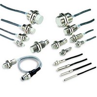
Proximity Sensors Metal Conn 2 Wire M12 Unshld
Manufacturer
Omron
Series
E2Er
Specifications of E2E-X8MD1-M1G
Proximity Sensor Type
Inductive
Proximity Sensor Sensing Distance
8mm
Proximity Sensor Sensing Distance Range
7 to 15mm
Proximity Sensor Switching Mode
NO
Mounting
Panel
Operating Temp Range
-25C to 70C
Operating Temperature Classification
Commercial
Operating Supply Voltage (min)
10V
Operating Supply Voltage (typ)
12/15/18/24V
Operating Supply Voltage (max)
30V
Pin Count
4
Maximum Operating Temperature
+ 70 C
Supply Voltage
24 V
Output Voltage
3 V
Operating Supply Voltage
12 V to 24 V
Mounting Style
Panel
Sensing Distance
8 mm
Minimum Operating Temperature
- 25 C
Maximum Output Current
100 mA
Features
High visibility indicator
Sensor Type
Inductive
Sensing Object
Metallic
Response Frequency
800Hz
Material - Body
Nickel-Plated Brass
Shielding
Shielded
Voltage - Supply
10 V ~ 30 V
Output Type
NPN-NO
Terminal Type
Connector
Package / Case
Cylinder, Threaded - M12
Lead Free Status / RoHS Status
Compliant


Diagram 20 E2E-X3D@-M1(G)
Diagram 22 E2E-X2Y@-M1
Diagram 24 E2E-X7D@-M1(G)/E2E-X5E@-M1/X5F@-M1
Diagram 26 E2E-X10D@-M1(G)/E2E-X10E@-M1/X10F@-M1
Mounting Hole Dimensions
* D1 Models:
D2/E/Y Models: Operation indicator (red)
42 dia.
21 dia.
21 dia.
29 dia.
* D1 Models: Operation indicator (red), Setting indicator (green)
F
D2/E/Y Models: Operation indicator (red)
17
36
17
24
E2E-X2E@-M1/E2E-X2F@-M1
E2E-X5Y@-M1
E2E-X10Y@-M1
Operation indicator (red), Setting indicator (green)
* D1 Models:
M30 × 1.5
D2/E/F Models: Operation indicator (red)
M12 × 1
M12 × 1
M18 × 1
Dimensions
4
4
5
F (mm)
4
38
33
Operation indicator (red),
Setting indicator (green)
Toothed washer
38
Toothed washer
Toothed washer
43
Toothed washer
48
53
Two clamping nuts
Two clamping nuts
53
Two clamping nuts
10
Two clamping nuts
58
10
10
10
Indicators *
Operation indicator (red)
Indicators*
Indicators*
8.5
M12 × 1
M12 × 1
M12 × 1
+0
M12 × 1
M8
0
.
5
dia. 12.5
M12
+0
0
.
5
dia. 18.5
Diagram 21 E2E-X8MD@-M1(G)
Diagram 23 E2E-X5MY@-M1
Diagram 25 E2E-X14MD@-M1(G)/E2E-X10ME@-M1
Diagram 27 E2E-X20MD@-M1(G)/E2E-X18ME@-M1/
M18
+0
0
.
* D1 Models:
5
D2/E/Y Models: Operation indicator (red)
29 dia.
42 dia.
dia. 30.5
21 dia.
21 dia.
* D1 Models:
17
D2/E/F Models: Operation indicator (red)
17
24
36
* D1 Models:
D2/E/Y Models: Operation indicator (red)
E2E-X5ME@-M1/E2E-X5MF@-M1
X10MF@-M1
E2E-X10MY@-M1
X18MF@-M1
E2E-X18MY@-M1
M30
Operation indicator (red), Setting indicator (green)
+0
14.8 dia.
26.8 dia.
0
9 dia.
9 dia.
.
5
Operation indicator (red), Setting indicator (green)
dia.
M12 × 1
M12 × 1
M18 × 1
Operation indicator (red), Setting indicator (green)
M30 × 1.5
7
7
10
13
4
4
4
33
38
38
43
5
Toothed washer
48
Toothed washer
53
Toothed washer
53
10
Two clamping nuts
58
Two clamping nuts
Two clamping nuts
Toothed washer
10
10
10
Two clamping nuts
Indicators*
Operation indicator (red)
Indicators*
Indicators*
M12 × 1
M12 × 1
M12 × 1
M12 × 1
E2E
34
Related parts for E2E-X8MD1-M1G
Image
Part Number
Description
Manufacturer
Datasheet
Request
R

Part Number:
Description:
Sensor; Inductive Sensing Mode; M8; NO 3-Wire DC NPN; 2; 12 to 24 VDC; Square
Manufacturer:
Omron Automation
Datasheet:
Part Number:
Description:
G6S-2GLow Signal Relay
Manufacturer:
Omron Corporation
Datasheet:
Part Number:
Description:
Compact, Low-cost, SSR Switching 5 to 20 A
Manufacturer:
Omron Corporation
Datasheet:
Part Number:
Description:
Manufacturer:
Omron Corporation
Datasheet:
Part Number:
Description:
Manufacturer:
Omron Corporation
Datasheet:
Part Number:
Description:
Manufacturer:
Omron Corporation
Datasheet:
Part Number:
Description:
Manufacturer:
Omron Corporation
Datasheet:
Part Number:
Description:
Manufacturer:
Omron Corporation
Datasheet:
Part Number:
Description:
Manufacturer:
Omron Corporation
Datasheet: