SS421L Honeywell, SS421L Datasheet
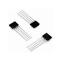
Board Mount Hall Effect / Magnetic Sensors 4.5Vdc to 16Vdc Magnet Position Sens

SS421L

Manufacturer Part Number
SS421L
Description
Board Mount Hall Effect / Magnetic Sensors 4.5Vdc to 16Vdc Magnet Position Sens
Manufacturer
Honeywell
Datasheet

Specifications of SS421L

Magnetic Type
Bipolar
Operating Supply Voltage (min)
4.5V
Operating Supply Voltage (typ)
5/9/12/15V
Operating Supply Voltage (max)
16V
Mag Sensor Operate Point (g)
250Gs
Mag Sensor Release Point (g)
-250Gs
Mag Sensor Hysteresis(g)
50Gs
Package Type
SIP
Pin Count
4
Mounting
Through Hole
Operating Temp Range
-40C to 125C
Operating Temperature Classification
Automotive
Operating Supply Voltage
5 V or 9 V or 12 V or 15 V
Supply Current
15 mA
Package / Case
SIP-4
Mounting Style
Through Hole
Maximum Operating Temperature
+ 105 C
Minimum Operating Temperature
- 40 C
Supply Voltage (min)
4.5 VDC
Supply Voltage (max)
16 VDC
Lead Free Status / RoHS Status
Compliant

Available stocks

Company
Part Number
Manufacturer
Quantity
Price
Part Number:
SS421L
Manufacturer:
HONEYWELL
Quantity:
10 000
FEATURES
• Wide temperature ranges
• Temperature
• Bipolar operation for easy
• Built-in timing circuit
• Speed trip point adjustable
TYPICAL APPLICATIONS
• Under-speed detection for
• Conveyors
• Motor control
• Power-up fault failure filter
PERSONAL INJURY
• DO NOT USE these
Failure to comply with
these instructions could
result in death or serious
injury.
Sensing and Control
Solid State Hall-effect Sensors
Adjustable Hall-Effect Under-speed Detectors
products as safety or
emergency stop devices, or
in any other application
where failure of the product
could result in personal
injury.
for design flexibility
compensated for
consistent operation with
low-cost magnets
RPM counting using ring
magnets
greatly simplifies and
reduces the cost of PC
board design
with external resistor and
capacitor
fans
in motor start-up
WARNING
designed to monitor fan or motor performance. This temperature-
compensated, Hall-effect IC contains a timing circuit and logic, that senses
magnetic input frequency. The internal circuitry contains a timer so that
one or two pulses at a slower repetition rate than the set point do not
produce an unwanted output.
operation right at the set point does not result in a chattering output. The
user simply provides an external resistor and capacitor combination to
select the RPM trip point that will fit the particular application.
inertial delay time for output switching. The SS421L has an inverting
output; the SS421H has a non-inverting output.
circuits. Built-in temperature compensation is optimized to match the
temperature coefficient of low-cost magnets and track their performance
over temperature.
high as 16.0 Vdc. The output is an open-collector NPN capable of
sinking 20 mA.
MISUSE OF DOCUMENTATION
• The information presented in this product sheet is for reference only.
• Complete installation, operation, and maintenance information is
The SS421 Series Adjustable Hall-effect Under-speed Detectors are
A small amount of hysteresis has been built into the output so that
External components are used to set the frequency trip point and
The small 4-pin package easily mounts on PC boards and flexible
The device will operate with supply voltages as low as 4.5 Vdc and as
Do not use this document as product installation information.
provided in the instructions supplied with each product.
Failure to comply with these instructions could result in death or
serious injury.
WARNING
SS421 Series

Related parts for SS421L

SS421L Summary of contents

Page 1

... RPM trip point that will fit the particular application. • Motor control • Power-up fault failure filter inertial delay time for output switching. The SS421L has an inverting in motor start-up output; the SS421H has a non-inverting output. circuits. Built-in temperature compensation is optimized to match the temperature coefficient of low-cost magnets and track their performance over temperature ...

Page 2

... Tp is the time delay after the pulses/min go above the trip point less than 20% of Td. HIGH SUPPLY VOLTAGE APPLIED AND HELD Figure 2. SS421L Timing Diagram Td is the time delay after the pulses/min go below the trip point set by the external RC the time delay after the pulses/min go above the trip point less than 20% of Td. HIGH ...

Page 3

... Honeywell • Sensing and Control 3 ...

Page 4

... Operate point is defined as the gauss level above which the internal circuitry will always be indicating the presence of a south pole at the IC surface. 3. Release point is defined as the gauss level below which the internal circuitry will always be indication the presence of a north pole at the IC surface. 4 Honeywell • Sensing and Control ( 1) Note Max ...

Page 5

... The open collector output can be used to drive external circuitry that applies a latching voltage to the program/oscillator pin to latch the IC output in the fail state. This latch mode used only on products with delay set times greater than five seconds and with inverted output version of the SS421L. 3. ...

Page 6

... ORDER GUIDE Catalog Listing Description SS421L Adjustable Hall-effect Under-speed Detector, Low (Speed > set point) SS421H Adjustable Hall-effect Under-speed Detector, High (Speed > set point) Figure 3. SS421L/SS421H Series Mounting Dimensions mm/in (for reference only 0,254 MAX OPTL [0.010] MICRO SWITCH CATALOG LISTING I.C. CENTER 2,41 [0 ...

Related keywords