B84111FB116 EPCOS Inc, B84111FB116 Datasheet - Page 13
B84111FB116
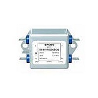
Manufacturer Part Number
B84111FB116
Description
FILTER LINE 250VAC 16A PANEL
Manufacturer
EPCOS Inc
Specifications of B84111FB116
Termination Style
Fast-On
Filter Type
Power Line
Voltage - Rated
250V
Current
16A
Mounting Type
Chassis Mount
Product
Inductors
Inductance
650 uH
Maximum Dc Current
16 Amps
Maximum Dc Resistance
6.8 mOhms
Dimensions
46 mm W x 72 mm L x 26 mm H
Current Rating
16A
Capacitance
100nF
Inductance Min
650µH
Svhc
No SVHC (18-Jun-2010)
Capacitance X Type Capacitor
0.1µF
Capacitance Y Type Capacitor
4700pF
External Depth
26mm
Rohs Compliant
Yes
Termination Type
Tab
Lead Free Status / RoHS Status
Lead free / RoHS Compliant
Lead Free Status / RoHS Status
Lead free / RoHS Compliant, Lead free / RoHS Compliant
Other names
495-3482


Caution and warnings
S Please note the advices in our data book “EMC Filters” (latest edition); attention should
S It shall be ensured that only qualified persons (electricity specialists) are engaged on work
S Danger of electric shock. EMC filters contain components that store an electric charge.
S The protective earth connections shall be the first to be made when the EMC filter is
S Impermissible overloading of the EMC filter, such as with circuits able to cause reso-
S EMC filters must be protected in the application against impermissible exceeding of the
S In case of leakage currents > 3.5 mA you shall mount the PE conductor stationary with
3) The KU value (symbol KU) is a classification parameter of safety referred failure types designed to ensure protection against hazardous
body currents and excessive heating.
A value of KU = 4.5 with respect to interruptions is attained:
KU = 6 with respect to interruptions is achieved for fixed connection lines w 10 mm
spond to the requirements for PEN conductors as specified in relevant standards.
4) I
Please read and Cautions and warnings and
Important notes at the end of this document.
with a permanently connected protective earth circuit w 1.5 mm
with a protective earth circuit w 2.5 mm
2 line filters
SIFI F for normal insertion loss
be paid to the chapter “General safety notes”.
such as planning, assembly, installation, operation, repair and maintenance. They must
be provided with the corresponding documentation.
Dangerous voltages can continue to exist at the filter terminals for longer than five min-
utes even after the power has been switched off.
installed and the last to be disconnected. Depending on the magnitude of the leakage cur-
rents, the particular specifications for making the protective earth connection must be ob-
served.
nances, impermissible voltages at higher frequencies etc. can lead to bodily injury and
death as well as cause substantial material damages (e.g. destruction of the filter hous-
ing).
rated currents by overcurrent protective.
the required cross section before beginning of operation and save it against disconnect-
ing. For leakage currents I
for leakage currents I
L
= leakage current let go
L
q 10 mA the PE conductor must have a KU value of 6.
2
L
connected via shroud connectors (IEC 60309 2).
4)
< 10 mA the PE conductor must have a KU value
Page 13 of 14
2
2
where the type of connection and line layout corre-
B84111F0000*
B84111-F0000-*-07-7659
3)
of 4.5;
Related parts for B84111FB116
Image
Part Number
Description
Manufacturer
Datasheet
Request
R


Part Number:
Description:
CAP .15UF 63V METAL POLY
Manufacturer:
EPCOS Inc
Datasheet:


Part Number:
Description:
CAP .01UF 400V METAL POLY
Manufacturer:
EPCOS Inc
Datasheet:
