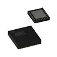
ATA6823-PHQY Atmel, ATA6823-PHQY Datasheet - Page 11

ATA6823-PHQY
Manufacturer Part Number
ATA6823-PHQY
Description
Motor / Motion / Ignition Controllers & Drivers Gate Driver IC
Manufacturer
Atmel
Type
H-Bridge Motor Driverr
Specifications of ATA6823-PHQY
Operating Current
7mA
Operating Temperature Classification
Automotive
Operating Supply Voltage (min)
7V
Operating Supply Voltage (max)
18V
Supply Current
7 mA
Mounting Style
SMD/SMT
Package / Case
QFN-32
Lead Free Status / RoHS Status
Compliant
3.6.2
3.7
3.7.1
3.7.2
3.7.3
4856K–AUTO–01/11
Control Inputs EN1, EN2, DIR, PWM
TXD Dominant Time-out Function
Pins EN1, EN2
Pin DIR
Pin PWM
The recessive BUS level is generated from the integrated 30k pull-up resistor in series with
an active diode. This diode prevents the reverse current of VBUS during differential voltage
between VSUP and BUS (V
No additional termination resistor is necessary to use the ATA6823 in LIN slave nodes. If this
IC is used for LIN master nodes, it is necessary that the BUS pin be terminated via an external
1k resistor in series with a diode to VBAT.
The TXD input has an internal pull-down resistor. An internal timer prevents the bus line from
being driven permanently in dominant state. If TXD is forced low longer than t
the pin LIN will be switched off to recessive mode. To reset this mode switch TXD to high (>
10µs) before switching LIN to dominant again.
Any of the enable pins may be used to activate the IC with a HIGH. EN1 is a low level input,
EN2 can withstand a voltage up to 40V. Internal pull-down resistors are included.
Logical input to control the direction of the external motor to be controlled by the IC. An inter-
nal pull-down resistor is included.
Logical input for PWM information delivered by external microcontroller. Duty cycle and fre-
quency at this pin are passed through to the H-bridge. An internal pull-down resistor is
included.
Table 3-1.
The internal signal ON is high when
In case of a short circuit, the appropriate transistor is switched off after a debounce time of
about 10µs. In order to avoid cross current through the bridge, a cross conduction timer is
implemented. Its time constant is programmable by means of an RC combination.
• At least one valid trigger has been accepted (SYNC = 1)
• V
• The charge pump has reached its minimum voltage (CPOK = 1) and
• The device is not overheated (OT2 = 0)
ON
0
1
1
VBAT
Control Inputs
is inside the specified range (UV = 0 and nOV = 1)
DIR
X
0
1
Status of the IC Depending on Control Inputs and Detected Failures
PWM
PWM
PWM
X
Driver Stage for External Power MOS
BUS
/PWM
OFF
ON
H1
> V
SUP
).
PWM
OFF
OFF
L1
/PWM
OFF
ON
H2
PWM
OFF
OFF
L2
Atmel ATA6823
Motor PWM forward
Motor PWM reverse
Standby mode
Comments
dom
> 18.4ms,
11


