■ Dimensions
Note: All units are in millimeters unless otherwise indicated.
11.5 0.2
■ Electrical and Optical Characteristics (Ta = 25°C)
Note: The letter “d” indicates the distance between the top surface of the sensor and the sensing object.
Emitter
Detector
Rising time
Falling time
Terminal No.
A
K
C
E
A
K
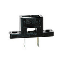
Photomicrosensor (Reflective)
EE-SB5(-B)
9 0.2
Internal Circuit
7.62 0.3
Anode
Cathode
Collector
Emitter
Forward voltage
Reverse current
Peak emission wavelength
Light current
Dark current
Leakage current
Collector–Emitter saturated voltage V
Peak spectral sensitivity wavelength λ
Name
C
E
Item
Four, 0.25
Two, 3.2 0.2 dia. holes
Unless otherwise specified, the
tolerances are as shown below.
3 mm max.
3
6
10
18
Dimensions
2.54 0.2
mm
mm
mm
mm
Optical axis
6
10
EE-SB5
18
30
Tolerance
Four, 0.5
0.3
0.375
0.45
0.55
0.65
V
I
λ
I
I
I
tr
tf
R
L
D
LEAK
Optical axis
P
P
F
CE
2.54 0.2
EE-SB5-B
Symbol
(sat)
Photomicrosensor (Reflective)
1.2 V typ., 1.5 V max.
0.01 μA typ., 10 μA max.
940 nm typ.
200 μA min., 2,000 μA max.
2 nA typ., 200 nA max.
2 μA max.
---
850 nm typ.
30 μs typ.
30 μs typ.
■ Features
• Dust-tight construction.
• With a visible-light intercepting filter which allows objects to be
• Mounted with M3 screws.
• Model with soldering terminals (EE-SB5).
• Model with PCB terminals (EE-SB5-B).
• RoHS Compliant.
■ Absolute Maximum Ratings (Ta = 25°C)
Note: 1. Refer to the temperature rating chart if the ambient temper-
■ Ordering Information
Emitter
Detector
Ambient tem-
perature
Soldering temperature
Photomicrosensor (reflective)
with soldering terminals
Photomicrosensor (reflective)
with PCB terminals
sensed without being greatly influenced by the light radiated from
fluorescent lamps.
2. The pulse width is 10 μs maximum with a frequency of 100 Hz.
3. Complete soldering within 10 seconds.
Value
ature exceeds 25°C.
Description
Forward current
Pulse forward current I
Reverse voltage
Collector–Emitter
voltage
Emitter–Collector
voltage
Collector current
Collector dissipation
Operating
Storage
Item
I
V
I
I
White paper with a reflection ratio of
90%, d = 5 mm (see note)
V
I
reflection
---
V
V
V
F
F
F
F
R
CE
CE
CC
CC
= 30 mA
= 20 mA
= 20 mA, V
= 20 mA, V
EE-SB5(-B)
= 4 V
= 10 V, 0 lx
= 10 V
= 5 V, R
= 5 V, R
I
V
V
V
I
P
T
T
T
Symbol
F
FP
C
opr
R
CEO
ECO
C
stg
sol
EE-SB5
EE-SB5-B
L
L
Condition
CE
CE
= 1 kΩ, I
= 1 kΩ, I
= 10 V
= 10 V with no
50 mA (see note 1)
1 A (see note 2)
4 V
30 V
---
20 mA
100 mW (see note 1)
–25°C to 80°C
–30°C to 80°C
260°C (see note 3)
Model
Rated value
L
L
= 1 mA
= 1 mA
233